For both the attenuator mounting, you are going to need your L-bracket, front panel, Grayhill nut and washer, (4) #4 nuts, (4) 4-40 1/2” flat screws, and (4) 1/4” standoffs. Mount the 1/2” machine screws and standoffs onto the L-bracket as shown.
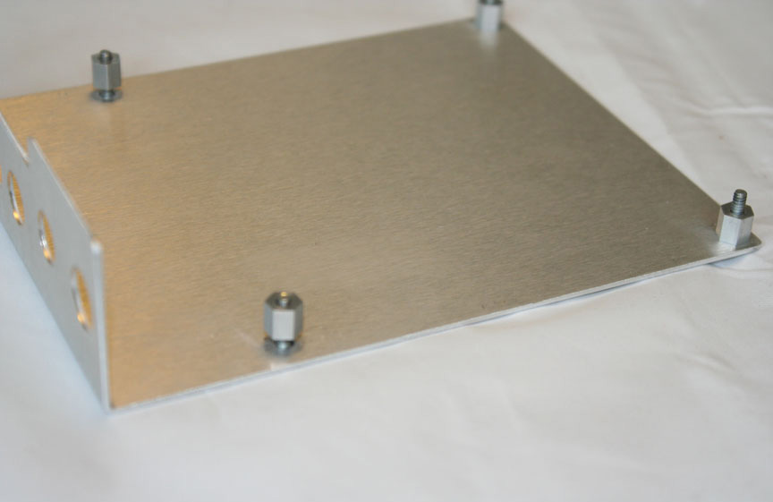
Do not tighten the standoffs so they are flush to the bracket. They need to be loose because we’ll need a little wiggle room shortly.
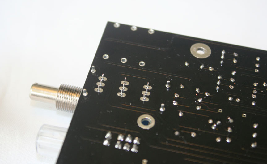
Next, insert the attenuator into the PCB. It’s not going to be easy, you have 9 PCB pins and 4 bracket pins that all need to line up properly. Take your time and use pliers to line up each pin. After a minute or two and 3-4 F-bombs you should have it in. Leave it floating off the PCB unsoldered.
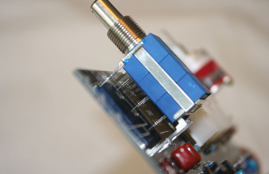
Now take the PCB and insert it at an angle into the L-bracket. Now place a #4 nut on each screw to set the PCB in place on the bracket.

At this point, there is no need to use the locking washer or over tighten. Just tighten the screw and nut enough to set the final mounting position.
Now slip the Lola front panel into place and hand tighten the Grayhill nut and attenuator nut.

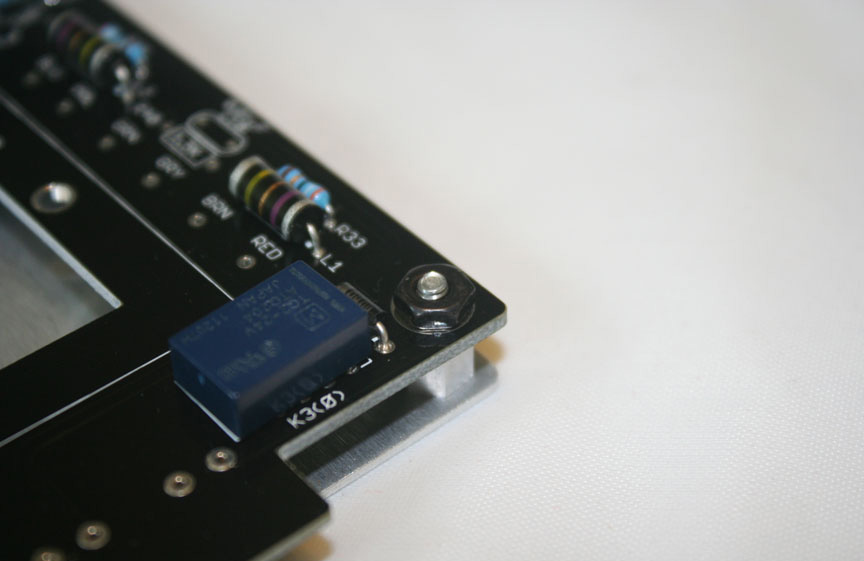
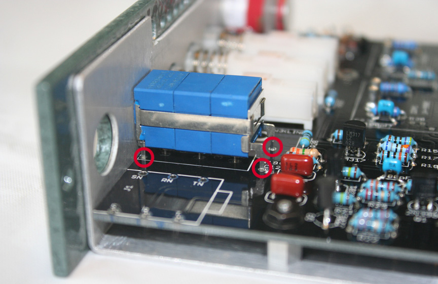
Again you don’t need to use the locking washers for this step. There is a little room to move the t-pad around in the hole. Position it so it’s as centered as possible with the scale before you tighten the nut. Your t-pad should now be at the right height for final soldering. With the front panel still attached, solder the three accessible t-pad rail pins from the top side. These are marked with red circles.
With these three pins soldered, your t-pad will be locked into place for final soldering. Remove the front panel and L-bracket. You can now solder the t-pad PCB pins and remaining unsoldered bracket pin from the bottom of the PCB. Be sure, as always, to trim and excess leads after soldering.