Calibrating your compressor is a crucial step to ensure its proper operation. There are several approaches to complete the four calibrations and I'll provide the way we like to do it here at Hairball.
For the Hairball method, you'll need a decent DMM that can read AC at 1KHz accurately. Usually, any meter over $30 can read 1KHz AC signals well enough. We're not calibrating a cruise missile.
To start, it's important that you understand the difference between dBFS and dBu. The calibration of the compressor requires the use of a signal generator and many users elect to use the signal generator inside of their DAW. The levels used by the DAW will be displayed in dBFS. dBFS is a digital reference with 0 dBFS being the maximum level the onboard A/D converter can achieve before clipping. dBu is an older reference that is defined with 0 dBu equal to 0.775 VAC .
Here's the scoop, there is no mathematical equation to convert dBFS to dBu since dBFS is dependent on the individual converter. That said, generally, 0 dBu can be found in the -16dBFS to -18dBFS range.
There's another problem, the FET Compressor has a very low nominal 600Ω input impedance. Generally, we want our input impedance (FET Compressor) to be at least 10x the source impedance (signal generator) to avoid impedance loss. With an input of 600Ω; this is rarely the case. Generally sending 0 dBu from your generator will result in a lower level at your input due to this impedance loss.
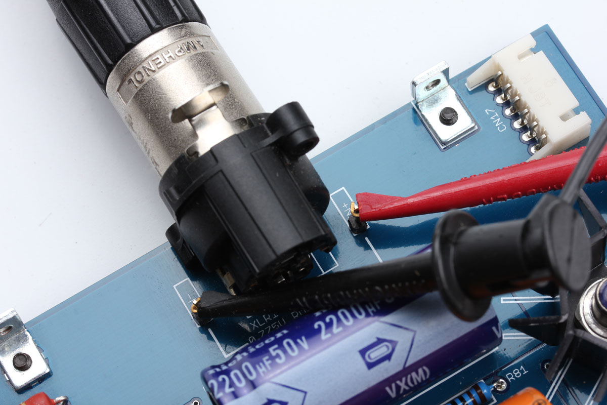
Confused? There is a simple fix for all of this. When asked in the calibration steps to send a 1K at 0 dBu signal to the input, use your DMM to measure the AC voltage between the IN + and IN - at the input XLR. Adjust your signal generator until you see 0.775VAC between these points. When you see 0.775 VAC between IN + and IN -, you have 0 dBu at your input.
Start by setting all trimmers, except QBias (see step 1), to their center position.
1. Q Bias (All Revisions)
Q-bias is easily the most important calibration step. Your compressor will not work without setting the q bias.
Here is how we set it at Hairball. Set the controls as follows.
Input = "24" mid rotation
Output = "24" mid rotation
Attack = full CCW (switched to off position)
Release = full CW
Compression ratio = 20:1
Meter mode = "GR"
Q-bias adjustment = full CW (Highest Output)
Apply a 1 KHz 0 dBu signal to the input and confirm with your DMM between IN + and IN - at the input XLR. Now move your DMM to the output XLR and measure AC between OUT + and OUT -. Adjust the output control to read +11dBu (2.75 VAC) on your DMM at the output. Slowly turn the Q-bias adjust (R59: Rev A /D and R81: Rev F ) CCW until a drop of 1 dB occurs, and your DMM reads +10 dBu (2.44 VAC). This places your gain reduction FET Q1 slightly into conduction.
2. Discrete Meter Circuit/Null Adjust (Rev A and D Only)
This step is only required for the Rev A and D. The Rev F uses an IC in the meter circuit and no Null adjust is required. If you have a Rev F skip to the next step.
Disconnect your signal generator. No signal is required for this step. Take R44 out of circuit by shunting the middle pin and pin not marked "normal operation".
Set your DMM to measure DC volts and set it to measure the DC volts across TP10 and TP11 for the Rev A and across R74 for the Rev D.
- Zero the compressors "GR" meter with the R71 zero adjust pot on the front panel.
- Adjust pot R75 (null adjust) for 0.0 Volts across TP10/TP11 (Rev A) or R74 (Rev D).
- Repeat 1 & 2 until both conditions are met.
Now set your shorting pin back to the "normal position" by connecting the two pins marked for "normal operation". Your meter will most likely drop a few dB. Set it back to zero by using the zero adjust pot on the front panel (R71). DO NOT touch the null adjust, it was set in the last step.
3. Reduction Meter Tracking Adjustment (All Revisions)
This step sets your meter tracking so if your compressor is compressing 10dB, you see -10dB on the meter. Confirm your meter shows zero on the meter with GR OFF. If needed set it to zero using the zero adjust pot on the front panel (R71: Rev A /D and R55: Rev F ).
Set controls as follows:
Input = "24" mid rotation
Output = "24" mid rotation
Attack = full CW
Release = full CW
Compression ratio = 20:1
Meter mode = "GR"
- Apply a 1 KHz, 0dBu signal, confirmed with your DMM at IN + and IN - at the input XLR (0.775 VAC).
- Move your DMM to OUT + and OUT - at the output XLR.
- Set output control for 0dBu (0.775 VAC) at the output.
- Set attack full CCW (off position). Set input control for +10dBu (2.44 VAC) at your output XLR.
- Turn the attack control ON (Fully CW) and readjust the output level control for "0dBu" if necessary.
- Now let's set the meter to display this 10dBu drop. When the attack is "off" (full CCW) and you see +10dBu at the output, set the meter to 0 by using the front panel zero adjust trimmer.
- When the attack control is "on" (full CW) and you see 0dBu at the output, use the tracking adjust (R44: Rev A /D and R54: Rev F ) to set the meter to -10.
- Repeat 6 & 7 until the output drops 10dBu whenever the attack control is turned ON. This can be a bit tricky. You'll want to anticipate how one control will change the other.
4. Distortion Trim (Rev D and F Only)
To adjust the distortion trimmer (R86: Rev D and R16: Rev F ), you need some specialized equipment that can measure Total Harmonic Distortion (THD). Sometimes you'll see it listed as THD+N which is the same measurement + noise. This calibration step is the least important. It might be the difference between having a THD measurement of 0.03% or 0.08%. If you can hear that, congratulations, you're superhuman. It does have some effect on your Q1 GR FET, but again it's minimal. If you don't have a way to measure THD, just leave the trimmer centered. If you have hardware or software to measure THD, here is how you calibrate it.
Input = Full CW
Output = to number "18" on the front panel
Attack = full CCW (switched to off position
Release = Full CW
Compression Ratio = 20:1
Meter mode = "GR"
Apply an input signal of 500 Hz at -30 dBu (0.024 VAC) and measure THD of the resulting output signal. Adjust trimmer until the minimum amount of distortion is achieved.
If all of the steps went well it's highly likely your compressor is working properly. Congrats! Now go, plug it in, and record some music!
Finding your input a little hot? Check out our Input Mod Page for some information and a solution.
Check out our FET/RACK Operational FAQ if you have any questions about how it's working.