Building the Active Link
This build guide assumes that you have already populated the FET/RACK PCBs and are familiar with basic electronic components and their installation. If you're not comfortable identifying and installing components please read through the FET/RACK assembly guide. Other than PCB color, there is no difference between the Rev A and Rev D active link PCBs.
Active Link Documentation
Below are helpful tools for completing the build. The interactive build map helps you locate and check off components as you populate the PCB. The searchable PDF BOM can be printed or opened and searched via your browser's search function. It also includes the schematic.
Active Link Interactive Build Map
Active Link Searchable PDF BOM, Schematic, Board Layout
*Note: For version 1.2 PCBs (marked on the PCB), C200 and C201 should be inserted backward. Meaning + into - and - into +. Installing, as indicated on the PCB, can lead to DC noise in the output pot. The silkscreen was fixed for version 1.3 PCB. For version 1.3 PCBs (and later versions), the caps should be installed normally.
Build Guide
Note: some components in your kit may look a little different (color, manufacturer) than the components in this guide.
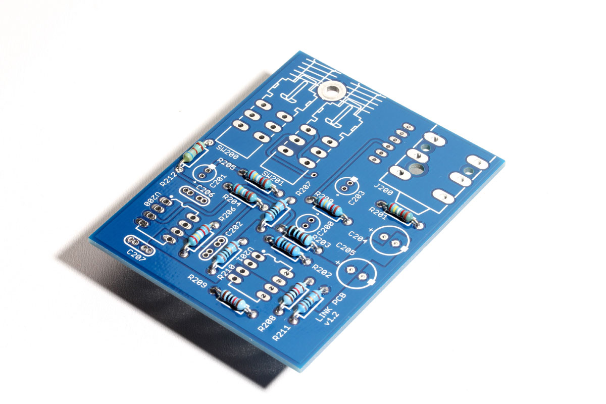
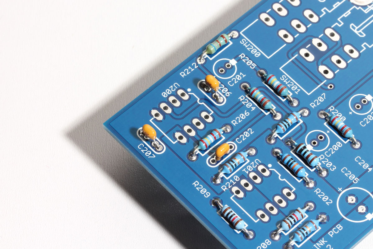
Start by installing the resistors.
Next, install the ceramic capacitors. The capacitors supplied with the kit are blue.
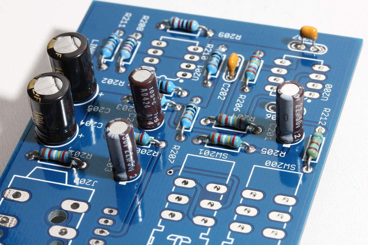
Install the electrolytic capacitors. Again, these are polarized and must be installed in the correct orientation. Note the long lead is positive and installed in the pad labeled "+" and the shorter negative lead is marked on the capacitor body and installed on the pad marked with a white box.
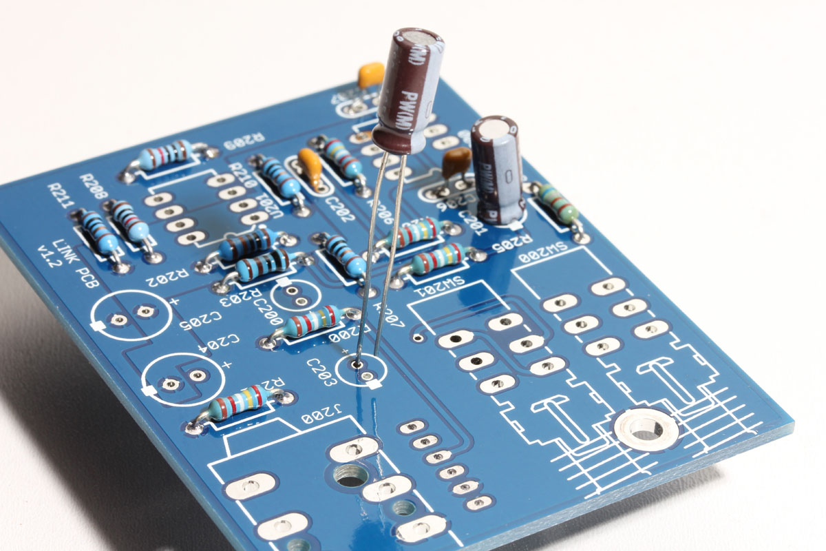
In the image below you can see the negative strip on the capacitor aligned with the white box on the silkscreen that indicates the negative lead.

Your PCB should now be populated with all of the resistors and capacitors.
Now install the two TL072 opamps. Your opamps will either have a half-moon shape or a dot at one end. In the case of the opamp below, it has both markings. This end (marked with a half-moon or dot) must be installed to match the half-moon shape and dot on the silkscreen.

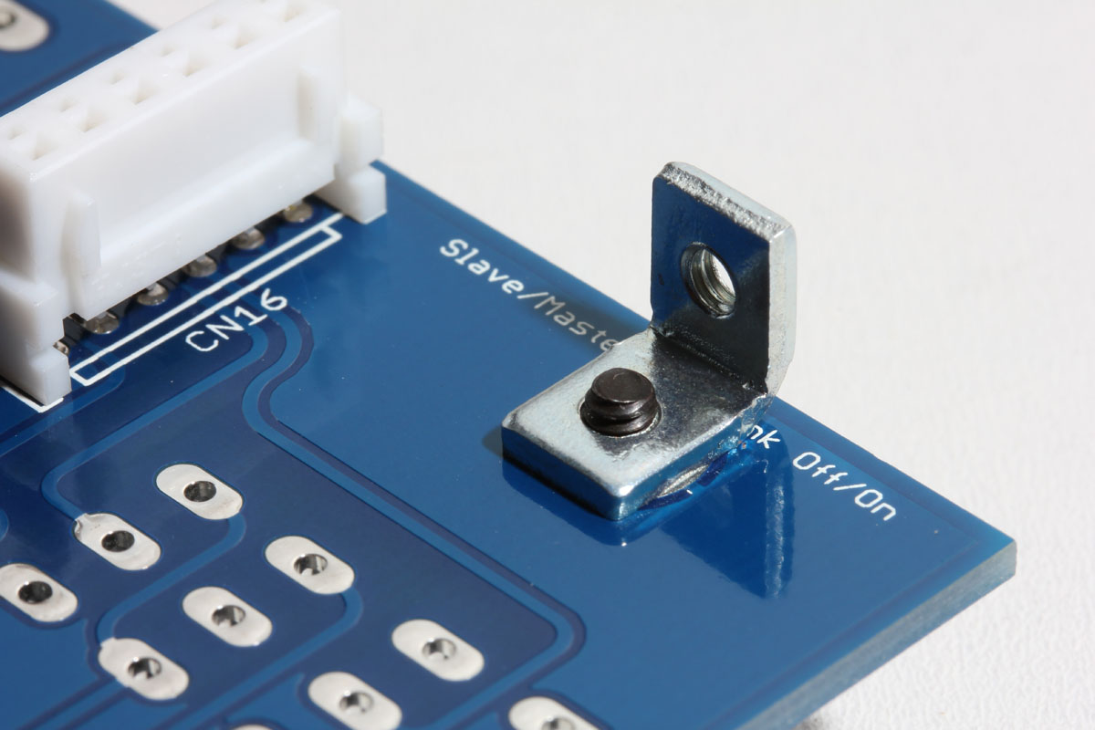
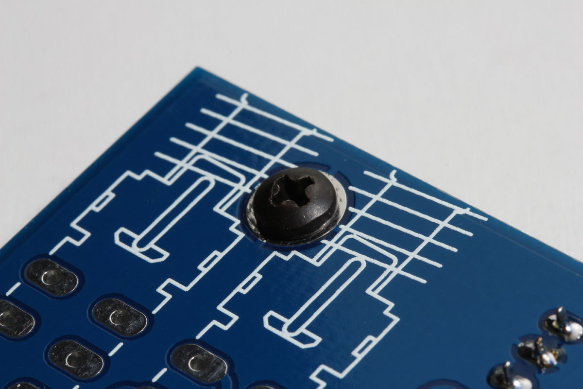
Now locate the L-bracket and #4 short silver pan screws. As noted in the FET/RACK build guide, the L-brackets are not symmetrical. One side is slightly longer than the other. Place the long side against the bottom side of the PCB and secure it from the top with a #4 short silver pan screw.
With the L-bracket in place, you can install the push button switches. Start by soldering one pin on each of the push button switches.
Confirm the switches are level and the plastic spacing tabs are tight to the PCB.

Check that the switches are parallel to the PCB edges and to each other.
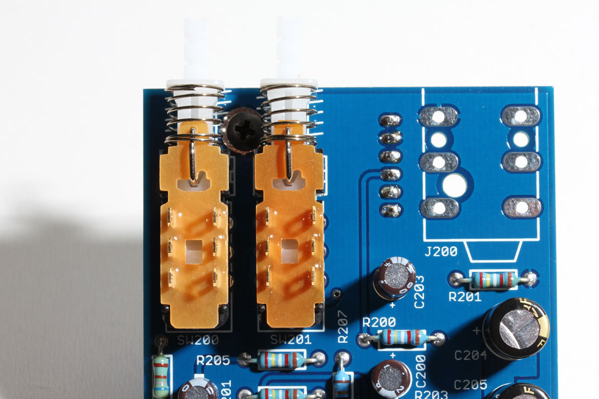
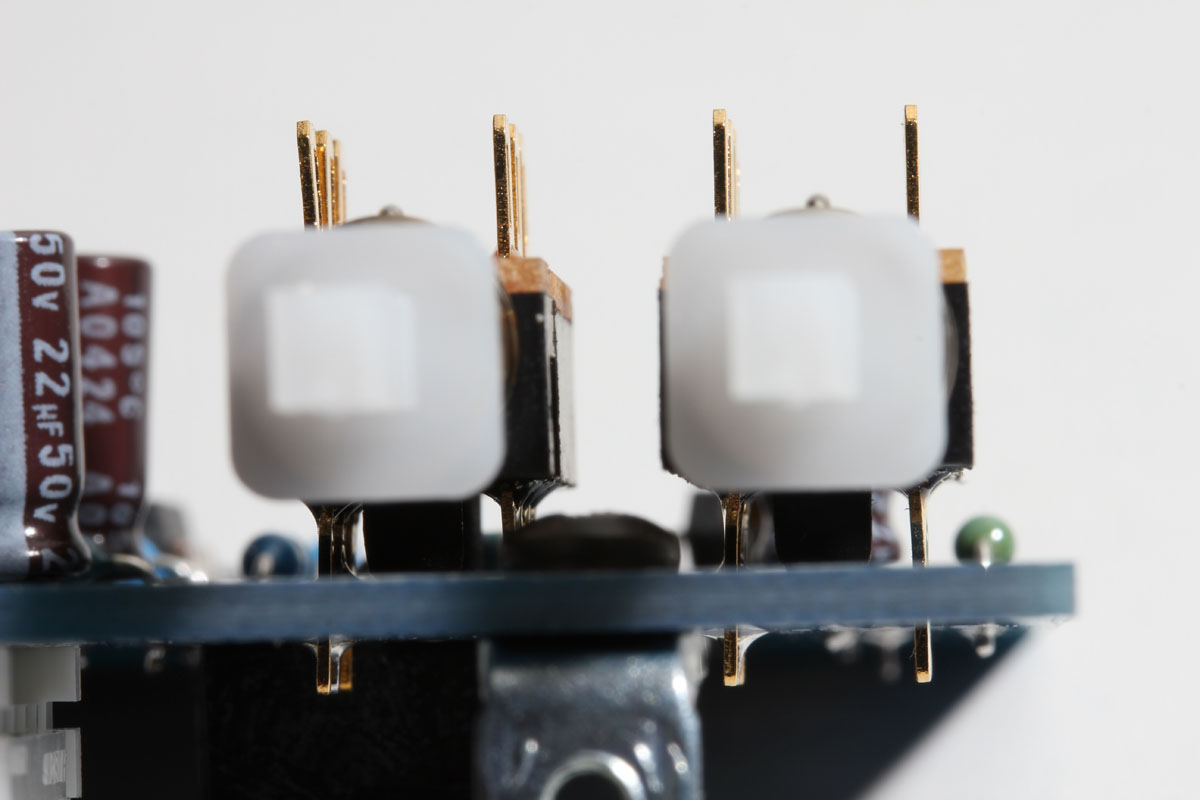
Once you're satisfied, you can solder the rest of the pins.
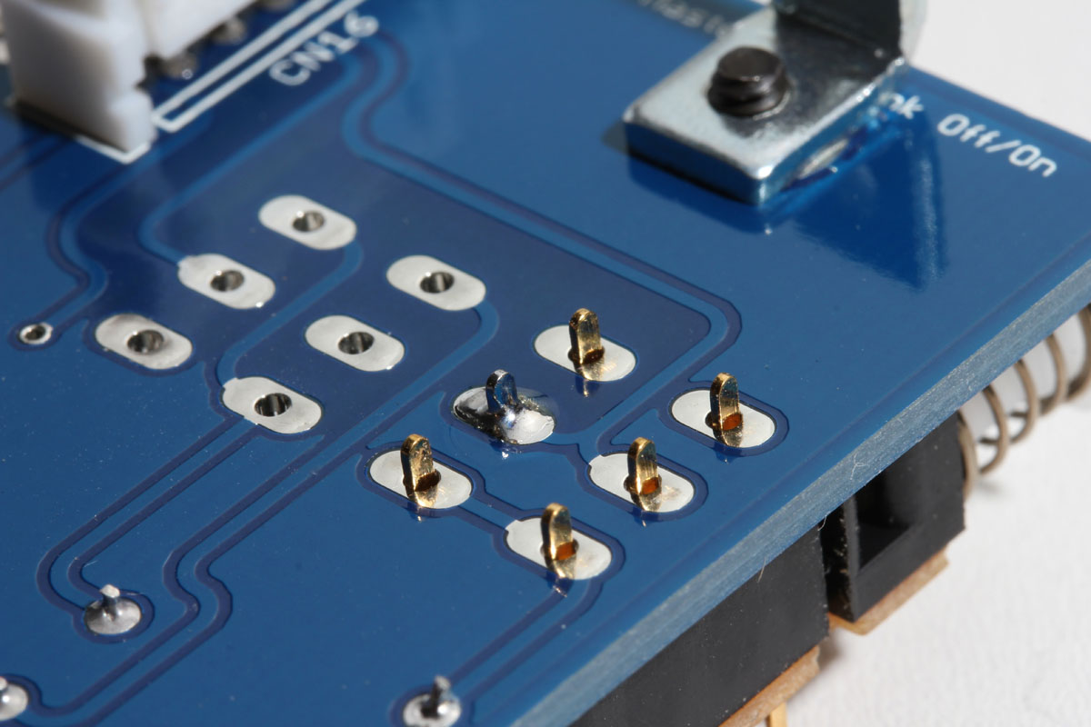
Finally, on the bottom side of the PCB install the 6-pin connector. Solder one pin and confirm it's flush to the PCB, then solder the remaining pins.
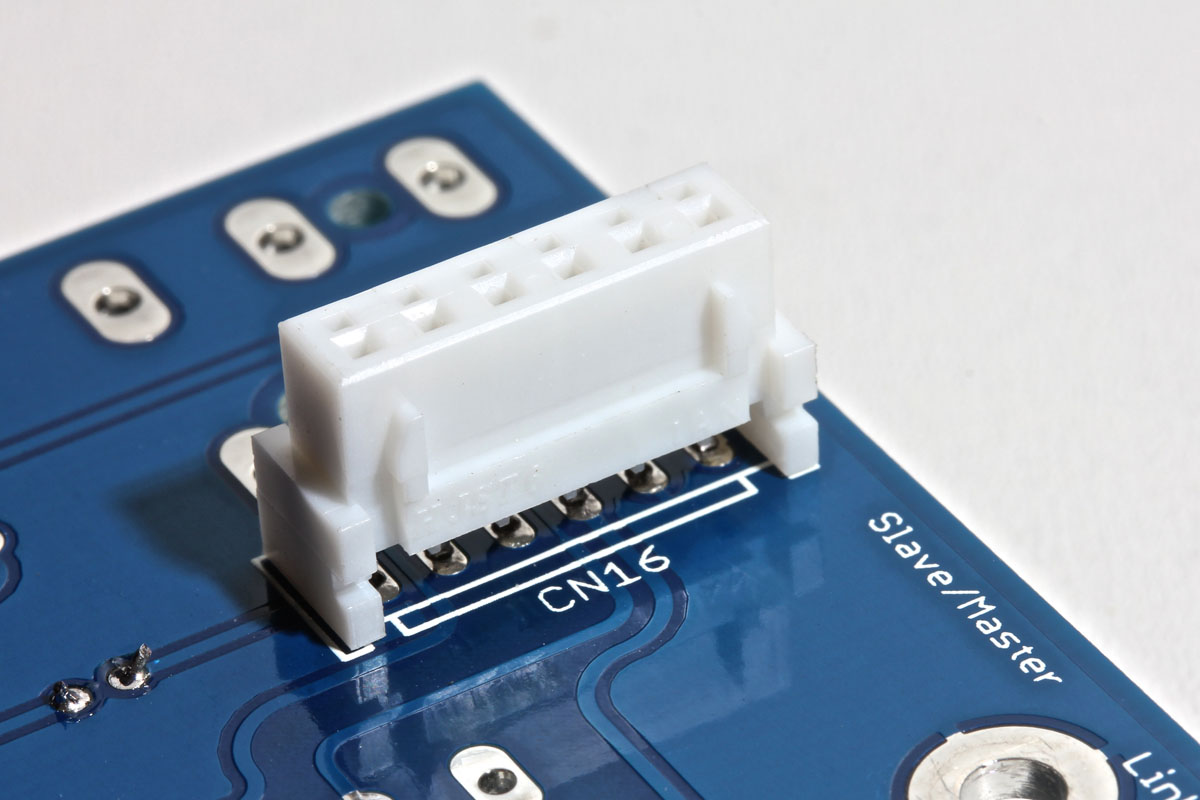
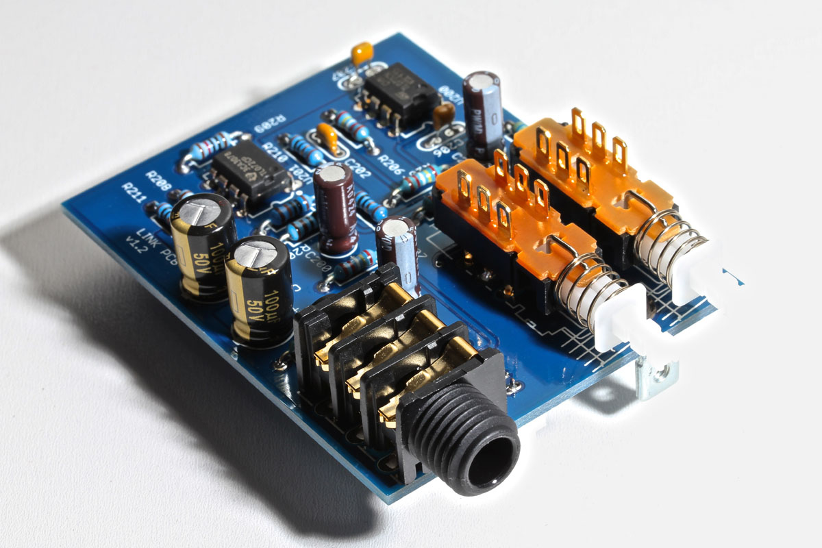
Your link PCB is now fully assembled!
With the link PCB attached for alignment, solder the right-angle connector to the main PCB. Note that on a batch of PCBs (late 2016/early 2017), CN17 had slightly too much plating in the holes making it hard/impossible to insert CN17 fully. If you have this issue, there is an easy fix. The outer pins (1 and 6) of CN17 have a little kink in them. Simply use a pair of needle-nose pliers to straighten out those two kinked leads, and CN17 will then press into place.

During final assembly, you'll use the remaining #4 short silver pan screw to secure the link L-bracket to the enclosure. You'll also apply the 1/4" jack nut and caps. Red for ON/OFF and black for SEND/RECEIVE.
Using Active Link
Passive and active link both have their advantages. The advantages of using active link include:
- unlike passive link, attack times are not doubled when using an active link
- does not require an external adaptor or calibration
- activate linking with the push of a button
- links easily to Purple Audio MC77
To activate linking, set both link PCBs to the ON position and set one unit to SEND and the other to RECEIVE. Start by matching the settings on both units. This includes input, output, attack, release, and ratio.
Once you have the desired compression you may notice that your GR is a little less in one unit due to side-chain tolerance differences. To get the two units tracking the same, you'll need to adjust the attack on one unit slightly. Typically adjusting the attack on one unit will make tracking worse, and the other will make tracking better.
Now that the units are tracking properly, they may have slightly different output levels. Using your DAW metering or +4/+8 on the FET/RACK units, adjust the output level using the output controls.