User Guide
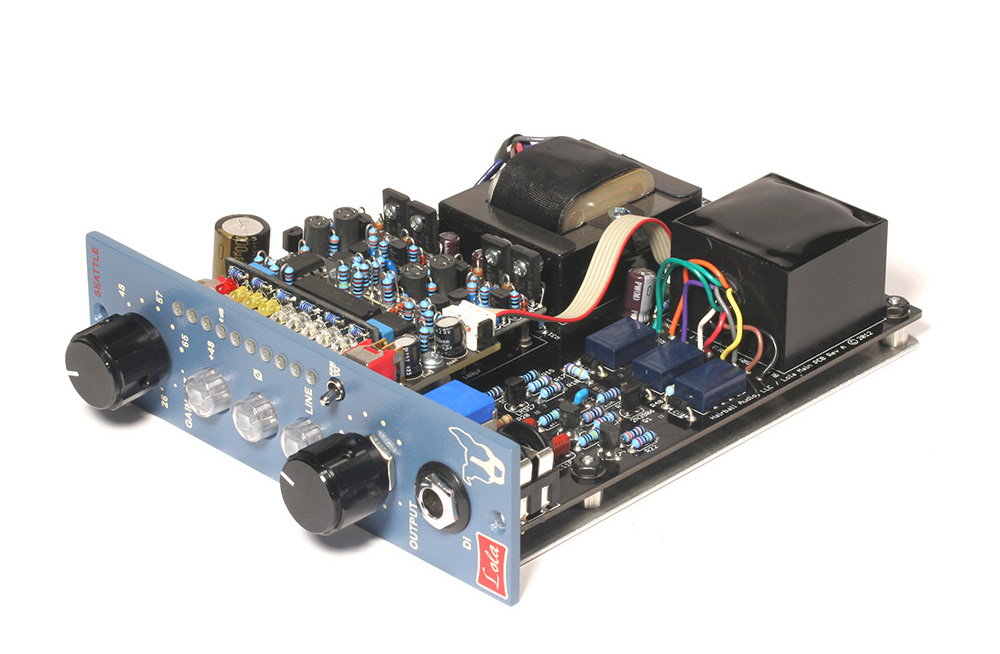
The Lola mic pre is a fully differential microphone preamplifier circuit featuring the EA-10468 input transformer, EA-1166 output transformer, and two discrete op-amps.
The Lola maintains a completely differential signal path from input to output. The benefit of this topology is lower noise and a high CMRR. It also takes advantage of the excellent balance of the EA-10468 input transformer. In addition, because there are two op-amps in parallel, the available output drive current is increased. This lowers output impedance; improving output transformer performance and increasing the maximum undistorted gain. In this regard, it’s similar to running a single op-amp design on 24V rails.
Gain
The gain stage provides 65dB of clean gain in 4.5dB steps utilizing a Grayhill rotary switch. With 48dB of adjustable gain, there is no need for an input pad.
Output
The 600Ω Bourns T-pad attenuator sits on the secondary of the output transformer and attenuates the output level while maintaining a nominal 600Ω load. This allows the user to fine-tune the output once the preferred gain setting is selected. It also allows the user to “push” the gain while maintaining an appropriate output level to add analog distortion to the source material.
Pushbutton Controls
There are three illuminated pushbutton switches to select phantom power, phase, and line mode.
The phantom power control (+48) provides +48VDC to pin 2 and 3 of the input XLR through two 6.8KΩ resistors. Phantom power is activated when the control is illuminated.
The polarity control (ø) flips the polarity of the source material by 180 degrees. The differential signal is phase flipped at the primary of the output transformer. This control uses a DPDT relay.
The line (LINE) control flips the primary and secondary of the input transformer making it a step-down input and reducing the overall gain by approximately 14dB. This allows the user to use the Lola on line level material. The line control uses two DPDT relays.
DI
The DI jack accepts a ¼” unbalanced cable. Inserting a cable triggers the DI relay to switch the input from the XLR input to the DI jack. The DI passes through 2 FET buffers creating a differential signal to feed the EA-10468 primary.
LED Meter
The Lola features a 10 segment integrated circuit controlled LED meter. Located below the meter is a toggle switch to select VU (low position) and Peak Programme Metering (high position). Though the VU mode is actually average metering (90% of RMS), it’s calibrated to VU metering with little effect on PPM mode. 0dB on the meter scale is equal to +4 dBu (1.23V) in VU mode. Peak mode displays the peak value of the waveform on the same scale.
Assembly Overview
Choosing to build your own piece of gear is a rewarding and great learning experience. If it’s your first time, this guide will walk you through all of the steps to complete your build. If you’re a grizzly old pro, you’re probably not even reading this!
Patience
Want to have a failed build and a huge headache? Rush through the build paying little attention to the instructions and be as sloppy as you can with your soldering and assembly. As much as you want that cool new piece of gear up and running NOW, take your time and take breaks. It’s the best way to ensure success with your build.
Tools
You’ll need a few basic tools to complete this build. Though this list may not be complete, it’ll give you an idea of what you should have on hand.
Soldering Iron
It goes without saying that you need a soldering iron. Get a decent one. At the very least you should have a 25-watt pencil-style soldering iron. Weller sells the WP-25 for about $40 USD and it’s a solid entry-level soldering iron. Radio Shack sells a 40-watt model for about $10 USD. I’ve not used that model, but I bet it’s better than a lighter.
If you’re going to build a few units and do some repairs, consider getting an adjustable temperature solder station. The Hakko 936 is a tried and tested unit that sells for about $70 USD. It’s a fabulous tool.
Soldering Tip
Most decent irons will allow you to insert different tip styles. For most PCB work, including this build, you’ll want a small chisel tip. I use the Hakko 936 iron with a D18-D16 tip. This is a 1.6mm radius chisel tip.
Solder
Solder is kind of like guitar strings in that you really need to feel which one is right for you. I went through a few types before I found one I liked. There are a few different considerations such as lead or lead-free, no clean type, and diameter. I use Kester #245 no clean solder. It is a 0.031” diameter 63/37 alloy. It needs no flux cleaning and is available at many local and online retailers (Part #24- 6337-8800).
Digital Multi-Meter (DMM)
A good DDM is as important as a soldering iron. An auto-ranging DDM will make sorting resistors a breeze and help avoid time-consuming errors.
Testing and troubleshooting will make having a good DDM a must. An inexpensive model is better than nothing, but a good model will be a trusted tool on your bench and in your studio for years. It’s important to note that cheap meters generally do not measure AC (audio) level accurately above a few hundred Hertz at best. In audio we like to deal with 1KHz test signals so get a nice meter.
Fluke is the standard for DMMs. A Fluke 177 is another tried and tested workhorse. It’s not cheap, but it’s not that expensive for something you will use and depend on every day.
Panavise
Do you need a Panavise? No. Will it make your PCB stuffing much easier? Yes. These are not that expensive. Consider getting one.
Pliers, Cutters, and Strippers
A pair of fine needle nose pliers will come in handy for some of the final assembly work. I bet you already have a pair of these!
Small diagonal cutters are a must. You’ll need these for trimming the component leads.
Having a decent pair of wire strippers in the 16-26 AWG range is something you should have.
1/16” Hex Key
Also known as a Hex Wrench, Allen Wrench, and Allen Key. Whatever you call it, you need one to install the knobs. Consider getting a set with a nice storage case.
Nut Drivers
These are not as fun as they sound. You need four: 1/4”, 5/16”, 7/16”, and 1/2”. These are used to tighten various nuts in assembly, including the front panel components. Due to the length of the Grayhill and T-pad shafts, you’ll need a nut driver with a fairly deep channel. I used to use pliers to tighten these. I’d mare the nuts, scratch the panel, and drop a few F-bombs. Do yourself a favor and get a Nut Driver set. I picked up a 7 piece set at a hardware mega-store for about $15.
Soldering Guide
Soldering WELL is one of those things that seems easy until you try it. Once you try, it starts to seem kind of difficult. Then finally you figure it out and it seems easy again.
Rather than trying to explain it to you, I went online trying to find the best video tutorial I could. I settled on Dave Jones’ tutorial on the EEVBlog. Dave’s a wacky cat, but so are most guys who inhale lead all day. The tutorial is presented in three parts: tools, soldering through hole components, and soldering surface mount components. For our purposes, I recommend you watch part 1 and 2. The videos are lengthy at about 25 minutes each, but they are well worth watching. Even I learned a few things.
The videos can be seen by visiting:
hairballaudio.com/eevblog-solder-tutorials
Component Sorting
If you like, you can print the pages below to assist you in sorting your components.
Gain Resistors
Main PCB Resistors
Main PCB Semiconductors
Main PCB Capacitors
Meter PCB Resistors
Meter PCB Semiconductors
Meter PCB Capacitors
Schematic
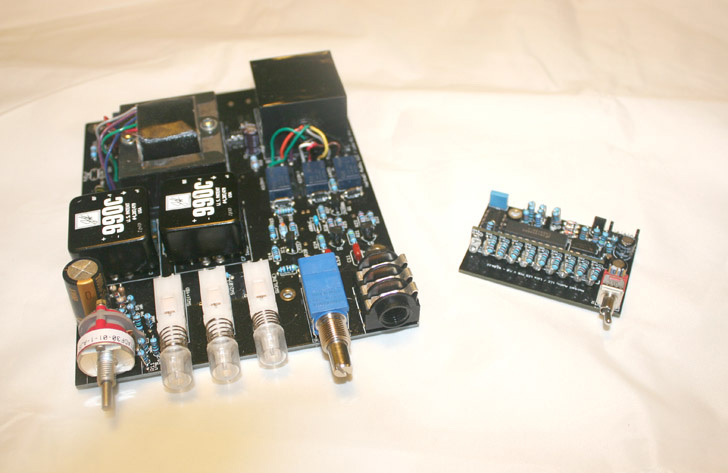
Populating the PCBs
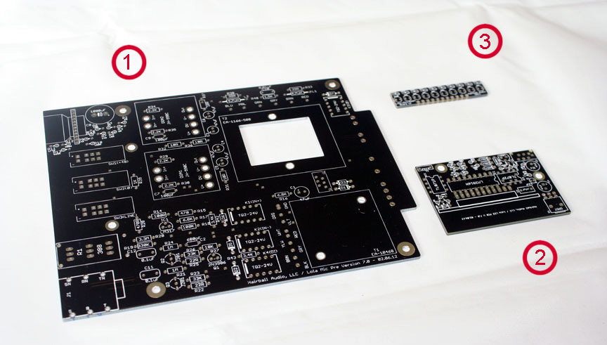
Your Lola mic pre is comprised of three printed circuit boards (PCBs):
-
Main PCB. Contains the mic pre circuit.
-
Meter PCB. Contains the LED meter circuit.
-
LED PCB. Contains the LEDs and current limiting resistors.
There may be some visual and numerical value differences between your PCBs and the PCBs used in this manual. The PCBs used in this manual are prototype versions.
Start by locating the main PCB.
Op-Amp Sockets
Let’s get started! Personally, I like to begin by inserting the op-amp sockets.
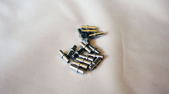
You should have 12 op-amp sockets in bag F, 6 for each op-amp. The sockets must be inserted from the top side (silkscreen side) of the PCB. This will ensure there is enough space between the op-amp and PCB surface for the feedback network that mounts under the op-amp.
There are a few different ways to solder the op-amp sockets. You can solder from the top, bottom, or both. The most important part is that you get good solder flow around the entire socket and PCB pad connection. I like to tilt my PanaVise so it’s parallel to my table surface with the silkscreen side up.

Place the sockets in the socket pads. The hollow end should be facing up, this hollow shaft accepts the op-amp pins. Working from the top side, place your solder tip so it makes contact with the socket and pad, just like you would with any other component. Be sure not to apply too much pressure to the socket or it may lift slightly causing it to sit slanted on the board. The socket is a large part that will need about 5 sec of heating time to get good flow. Applying a touch of solder to the solder tip, PCB, and socket connection point should allow for good heat transfer (see 20:00 of solder video 2). When you start to see that solder flow, apply some solder to the opposite side of the pad while keeping your iron tip in the original location. This should give you a good flow around the pad. Remember less is more when it comes to solder. If you’ve achieved a good connection on the top side there is no need to solder the bottom side. Once you have all the sockets soldered, you can wiggle them to confirm you have a good electrical and mechanical connection.
Gain Resistors
Next, let’s stuff those gain resistors!
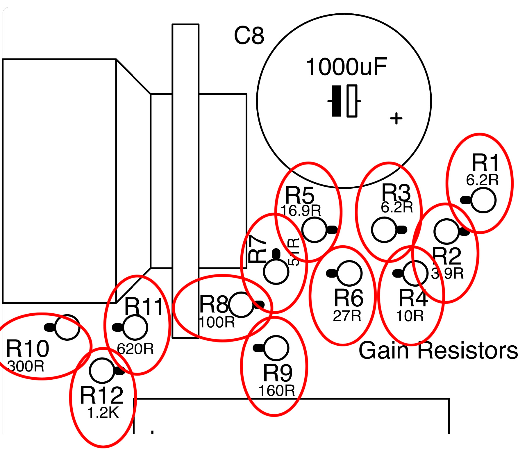
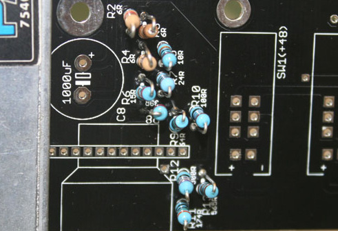
These are the 12 resistors that set the gain of the Lola mic pre. They are located near the Grayhill switch and are labeled R1-R12. Because of the tight spacing in this region of the PCB, these resistors are mounted vertically.
Start by removing the 12 resistors from bag D and check them with your DMM. You can insert them in any order you like, but doing them in order R1-R12 might help you avoid mistakes.
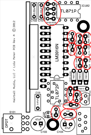
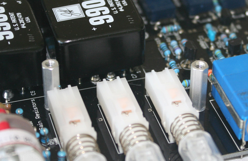
It can be a little tricky to identify the resistor placement, so use the detailed view above to confirm you have the resistors in the right location. Start by using your finger to bend one of the resistor's legs 180 degrees back towards the resistor.

The vertical resistor symbol has a circle around one pad and a line the points to a pad without a circle. The resistor body sits on the pad with the circle surrounding it.
The circle represents the resistor body and the line points to the pad where you will insert the other lead.
These parts are not polarized, they can be inserted in either direction. Following the silkscreen footprint simply helps avoid exposed legs from touching and creating a short. Once the component is soldered to the PCB you can trim off any remaining leads.
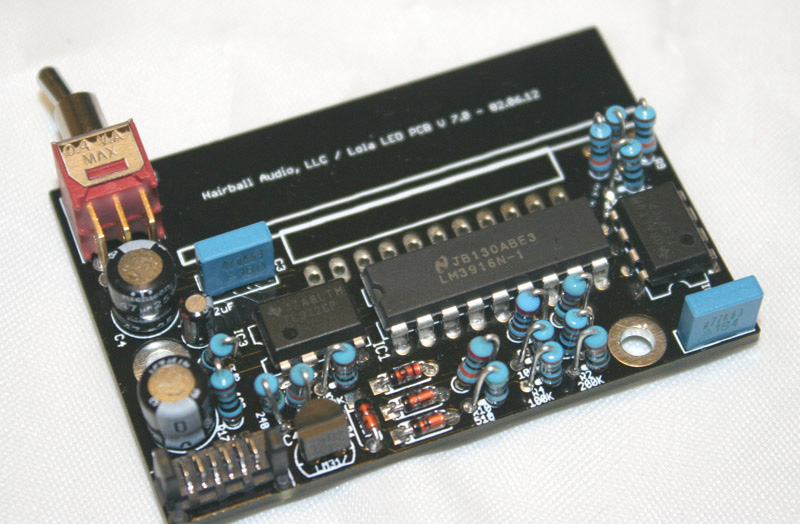
When you’re done you’ll have something similar to the image below.
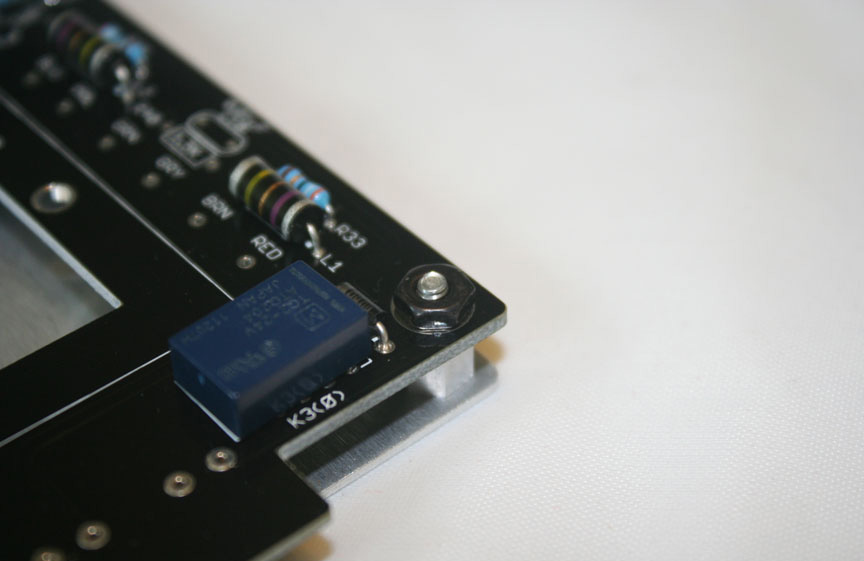
Main PCB Resistors
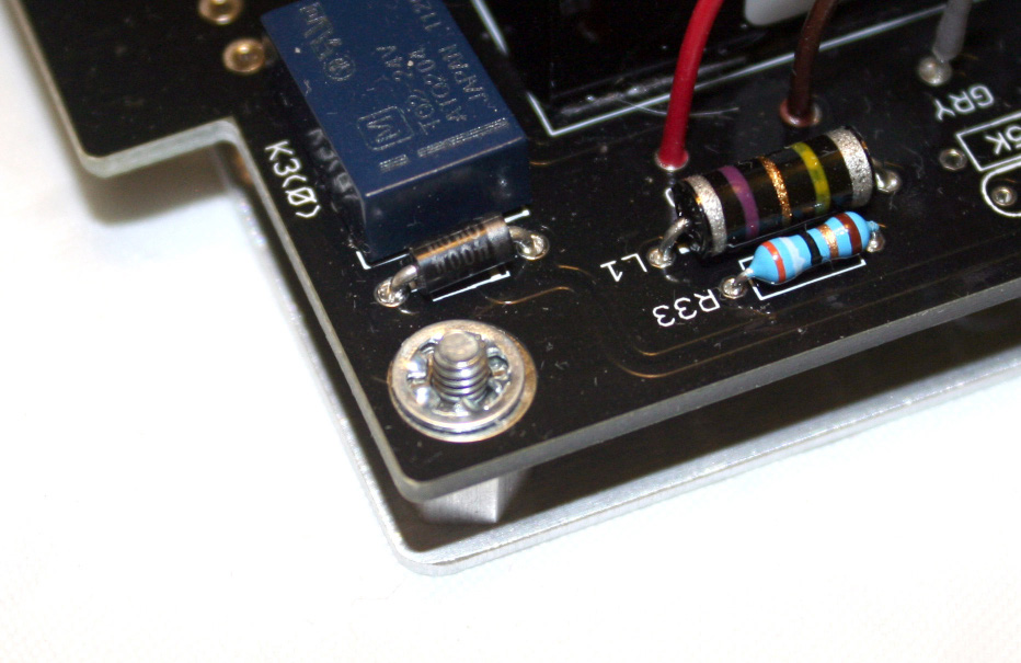
Now let’s go ahead and stuff the rest of the horizontal resistors located in bag E. Note that there are two 4.7 uH inductors. The current kits ship with green inductors shown here next to R33 and R38. If you have an older kit, they will be dark brown and look similar to old carbon resistors.
These are not resistors and cannot be tested using the resistance tester on your DMM. Since there are only two and they are of identical value there is no need to test them. Simply install them as you would a resistor. Placed in parallel with 39Ω resistors, these create an output isolator between your op-amp out and output transformer.
Use extreme care when testing and sorting your resistors! Check every resistor twice. It may take you an extra couple of minutes now, but it can save you days of troubleshooting to find where you mistakingly swapped a 10KΩ for a 10Ω. Take your time and get it right the first time.
It's important to note however, that not all meters are created equal. Even great meters do not measure high resistance or very low resistance accurately. Everything has a resistance/impedance, including your meter reading input. When measuring a resistor, its input resistance is in parallel with the resistor under test. For practical purposes, low input resistance meters (1M) will measure resistors 10K or above as having a lower resistance. Meters with higher (10M<) resistance will read accurately into the mega ohms but still have their limitations (3Mohms or higher).
Measuring lower resistance is problematic because your meter leads themselves have resistance. Resistors under 10Ω may measure a few ohms higher from added lead resistance.
It should be noted that resistors are rarely defective out of the box. If you read the color codes, you'll only need the meter to double-check. Just be aware that at higher resistance your values may measure lower. It's your meter.
Digikey.com has a great calculator tool to help you with color codes. Most of the resistors in the kit are 5 band blue metal film resistors.
The larger values are the beige carbon comp 4 band resistors.
The pad spacing for the horizontal resistors, diodes, and inductors is identical to the body length with one exception being the green inductors. This allows us to avoid any specialized bending jigs. Just use your fingers to apply bending force to the leads while holding the body.
Carefully work your way through the circuit. Again double, or even triple, check all of your resistor values and numerical designations.
Semiconductors
Let’s talk semiconductors. These are located in bag B. There are 6 protection diodes on the main PCB. They make sure current is flowing the right way in your Lola. There is one across the power terminals of each relay and one on each of the 16V power rails. They are installed just like a resistor with one MAJOR difference, they are polarized. Meaning they must be installed in the proper direction. Luckily this is pretty simple. All you need to do is line up the grey stripe on the diode with the stripe on the diode
The remaining TO-92 package semiconductors get installed by following the silkscreen footprint on the PCB. These include the LM317 constant current source for the LED pushbutton switches, the 2N3906 relay trigger, and two 2N5457 or J201 DI FET buffers.
Relays
Once you’ve installed the semiconductors we can move on to the relays in bag C. These are the electromechanical switches that do all kinds of crazy things inside the Lola circuit.
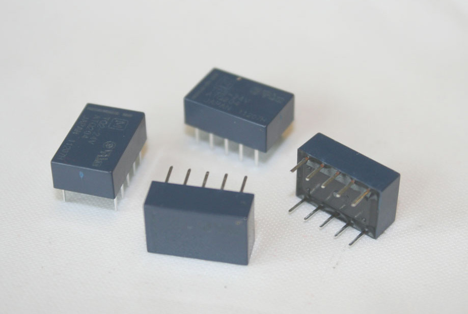
K1 and K2 work in tandem. They are triggered by the “Line” pushbutton switch and their job is to flip your input transformer from a mic in (step up) to a line in (step down). I told you they do crazy things! K3 is the phase reverse and is located between the op-amp outputs and output transformer primary. It, of course, is controlled by the “Phase” pushbutton switch. K4 switches the Lola input from the XLR into the 1/4” DI jack. This one is different in two ways. First, it’s not switched by a pushbutton switch. It’s triggered when you insert an unbalanced cable into the 1/4” DI jack. Second, it’s normally “on”, meaning current is flowing through the relay and breaking the ground connection with the DI jack turns it “off ”. That part really isn’t important, but you may hear it “click” on when you power up your Lola.
Enough of this crazy circuit talk, let’s stuff that PCB! When inserting the relays orientation matters. Like the diodes, make sure you align the white line of the relay with the line on the silkscreen layer.
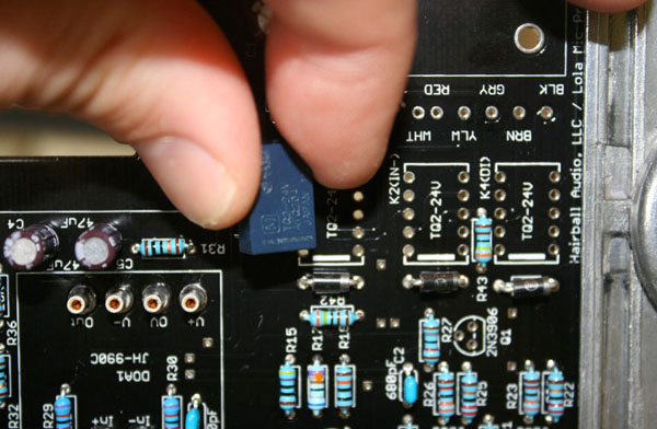
Once you have them slipped into place, flip your PCB and bend back a couple leads to hold them in place while you solder.
The leads are small enough that they don’t need to be clipped.
Capacitors
There are a handful of capacitors in the Lola, certainly a lot less than many circuits you may have encountered. This is a real advantage since it is generally perceived that the fewer capacitors you have in your audio path, the better. The capacitors are located in bag A.
There are two op-amp feedback capacitors and one input Zobel network capacitor. These capacitors are the small blue multilayer ceramic capacitors.
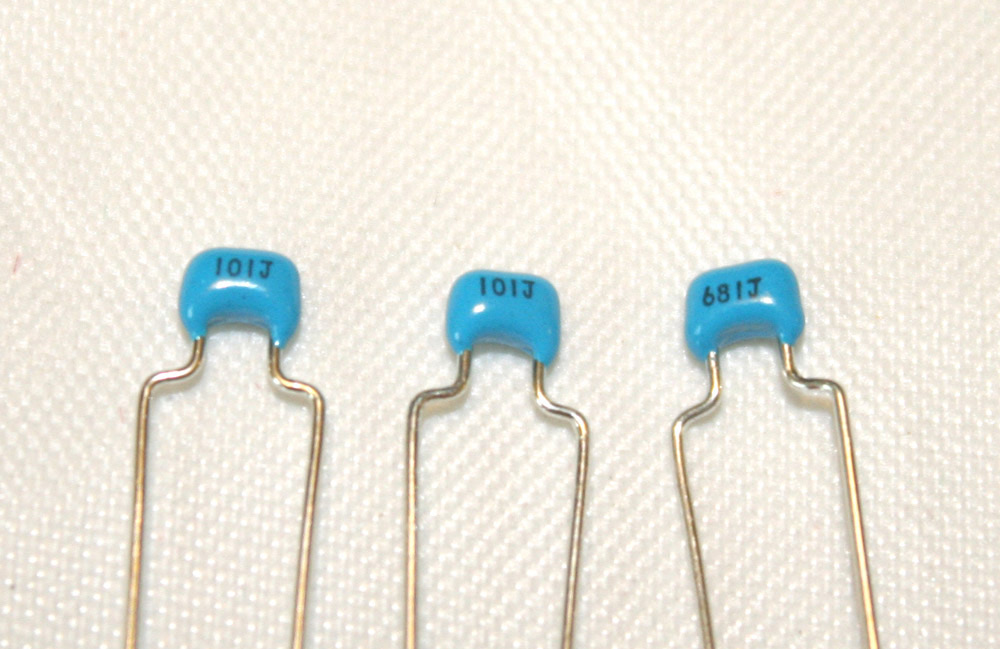
To Identify which two are the 100pF feedback capacitors (C7 and C9) and which is the 680pF input transformer Zobel capacitor (C2) we’ll have to do some tiny reading. Some are VERY hard to see, but they are there on one side. If you can't see the numbers take them outside or in brighter light. These capacitors are too small to measure properly with a common DMM. The two 100pF feedback caps will have the value 101J printed on them. The Zobel cap will have the value 681J printed on it. Once you have identified them, you can insert and solder them. They are non-polarized capacitors so the orientation is not important.
Now move on to the two grey film capacitors. These are two 0.1uF capacitors (C10 and C11) used to block DC from the DI buffer circuit. They have the value 104 printed on them.
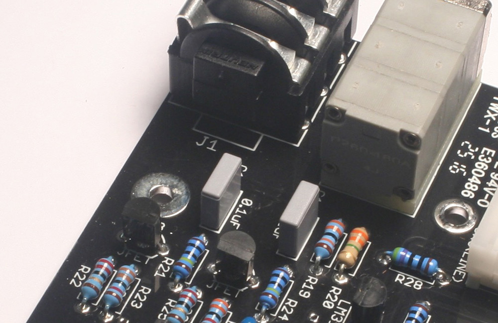
These are also non-polarized and can be installed in any direction.
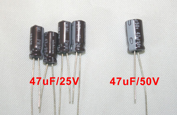
Since we have op-amps we should probably add some bypass capacitors. This is usually done with a 0.1uF and a 47uF on each op-amp power supply pin to ground. The JH-990 has the 0.1uF bypass capacitors inside the op-amp (awesome), so all we need to do is add some polarized 47uF electrolytic capacitors to each op-amp power supply pin. These are the 47uF/25V polarized electrolytic capacitors (C3, C4, C5, and C6) in your kit.
Use extreme care when inserting these capacitors. They are polarized and must be inserted with the proper polarity. Failing to do so will result in a small match like fire and a stink you won’t be able to get rid of for days.
Along one side of the capacitor there is a gray stripe containing several “-” or negative symbols. That stripe lines up with the negative terminal. On your PCB, one of the pads will have a “+” or positive symbol beside it. This is the pad that will receive the positive lead. Another indicator is that the square pad is for the positive lead and the round pad is the negative lead.
Next up is the 47uF/50V capacitor for the phantom power circuit (C1). It looks similar to the previous capacitors except it is slightly larger and rated for the 48V phantom power supply (Fig 15). It is also polarized so be sure to insert it correctly before you solder.
You still have a giant 1000uF (C8) polarized capacitor in your kit but let’s set that one aside for now. It can interfere with your PanaVise so we’ll install it towards the end.
Ribbon Header
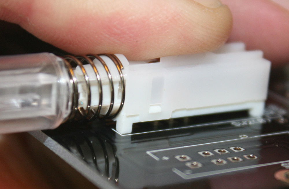
Now is a good time to insert the header for the ribbon cable that connects your main PCB to your Meter PCB.

It’s located in the large Meter package in bag D. There are two but you just need one for now.
Inserting this connector should be fairly straightforward. Obviously, you do not solder the plastic locating pegs. When soldering the 6 connector pins try to work fairly quickly to limit the heat applied to the header material.
If you have not done so already, TAKE A BREAK. You’ve reached a pretty big milestone!
Most of what’s left are the larger parts. You’ll need to take your time to get through these so try to avoid rushing at this point.

If you have an older PCB, you may have noticed that there is a capacitor labeled “OPT-C” and a resistor labeled “OPT-R” that you’ve not populated on your PCB. This is the optional output Zobel network that ended up being redundant. Just leave it empty, it's been removed from the current PCBs.
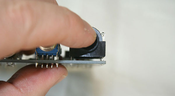
Pushbutton Switches
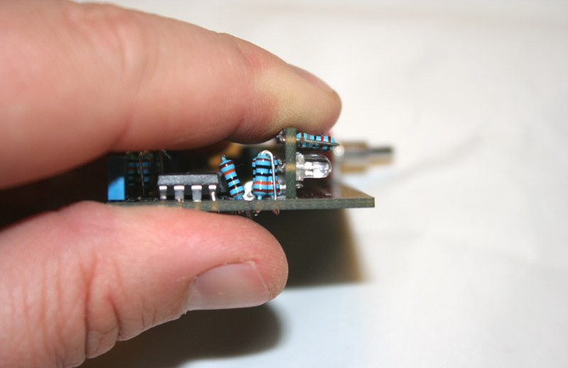
Let’s mount the switches. The three illuminated pushbutton switches (SW1, SW2, and SW3) are polarized. However, they can only be inserted in one direction. The most important thing to ensure when mounting these switches is that they are sitting completely flush with the PCB surface.
Notice how the four feet of the pushbutton switch are pressed flush to the PCB surface. Since the switches are designed to snap into place, they should naturally sit flush. Just make sure not to push them out when you solder the pins on the reverse side. These need to be flush to match the pushbutton holes on the L-bracket and front panel.
Grayhill Gain Switch
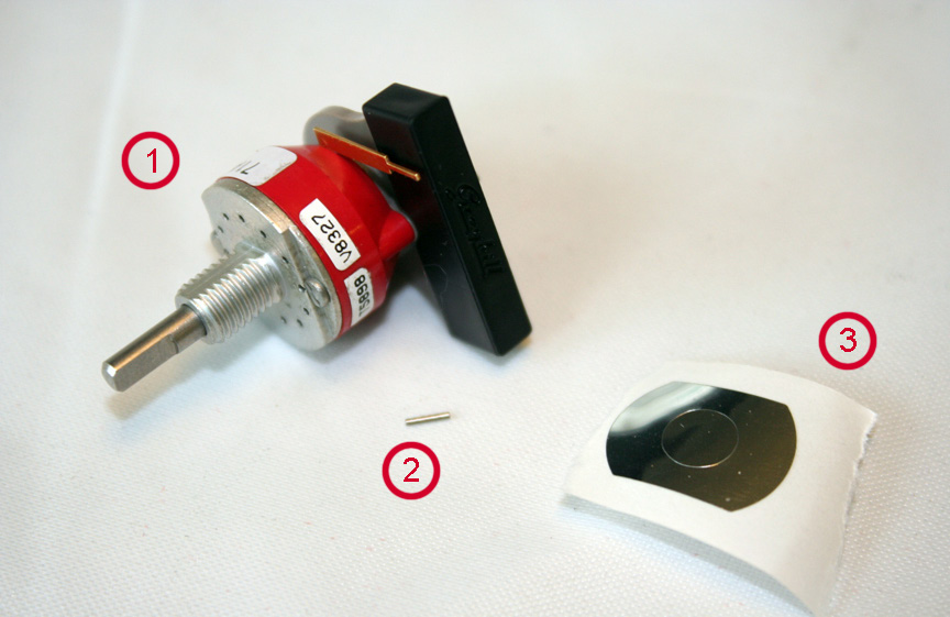
Let’s talk about the gain switch. It’s a single deck 12 position shorting Grayhill rotary switch. This switch sits between your op-amp feedback networks and allows you to select a gain range from 16.5dB - 65 dB in 4.5 dB steps. There are three parts to the Grayhill assembly.
-
The Grayhill Switch w/ Nut and Washer
-
The Stop Pin
-
The Retaining Sticker
Remove the nut and washer and set them aside in a safe place. Your kit may have included 2 stop pins. You only need one, but keep the other handy. If you drop one you’ll never find it. Before it gets lost, let's insert that stop pin. Without the stop pin the switch will just endlessly turn. When you get to the maximum gain setting it will allow you to turn through to the lowest setting. Maybe you want that? Then don’t insert the pin. However, most people would probably find this annoying so let’s get it in there. It needs to be placed in a specific hole that will tell it which position is the end position. Hold the switch so that the PCB mounting pins are facing down and place the stop pin in the 12 o’clock position. Needle nose pliers work well for this step.

Push the stop pin into the hole until it sits flush with the switch surface. Next, peel the retaining sticker from its backing and place it over the shaft and on to the switch surface.

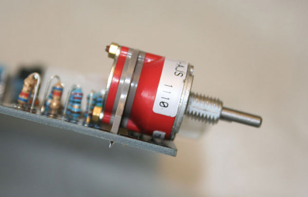
Remove the plastic PCB pin protective covering and insert the Grayhill into the PCB. Like the pushbutton switches, they Grayhill switch must sit flush to the PCB. Try to keep it as upright as possible so that the shaft is parallel to the PCB surface. There will be a little room for fine-tuning once the component is soldered in place. For now, make sure it is pressed flush to the PCB.
If it looks something like below, then well done!
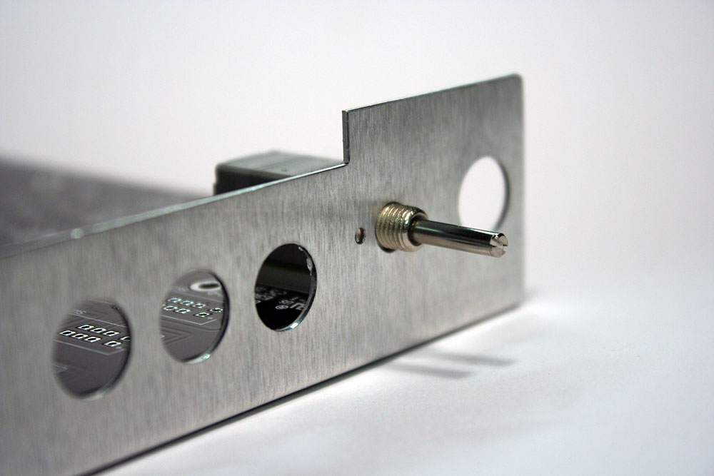
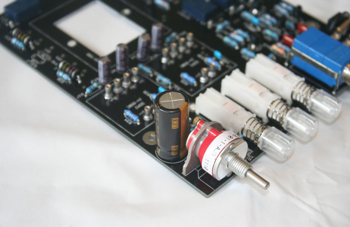
Output Attenuator
Between the output transformer secondary and the output XLR you’ll find a 600Ω T-pad attenuator. The default position should be the fully clockwise position. The attenuator accomplishes three things.
-
Allows you to fine-tune your gain setting within the 4.5dB Grayhill switch steps.
-
Allows you to lower the output signal when pushing the input gain so the Lola distorts (good) while protecting your A/D converters from distortion (bad).
-
Maintains a nominal 600Ω impedance on the output transformer secondary. This will keep Lola happy.
Locate the 3-deck grey T-pad and PCB spacer. Slide the PCB spacer onto the pins of the T-pad.
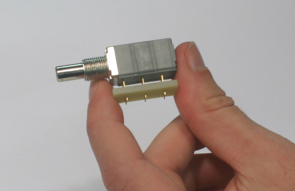
It’s made to slide on in any direction. Next, sandwich the spacer between the T-pad and PCB and solder the 9 T-pad pins on the bottom side. Make sure it’s all snug against the PCB. Easy!
Kits ordered between mid-June 2016 and late-October 2016 will come with an L-bracket that has a 1/4" T-pad hole and no anti-rotation lug hole.
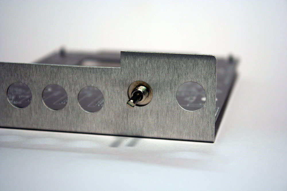
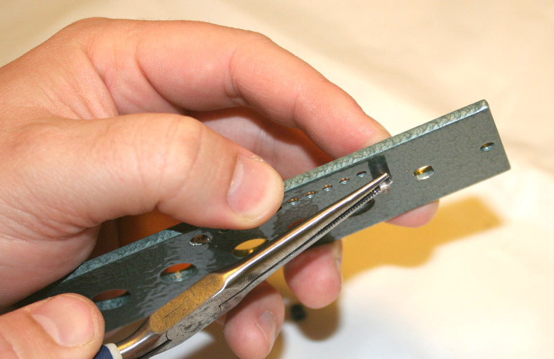
If your bracket looks like the one above, you'll need to completely cut off the anti-rotation lug so the L-bracket sits straight.
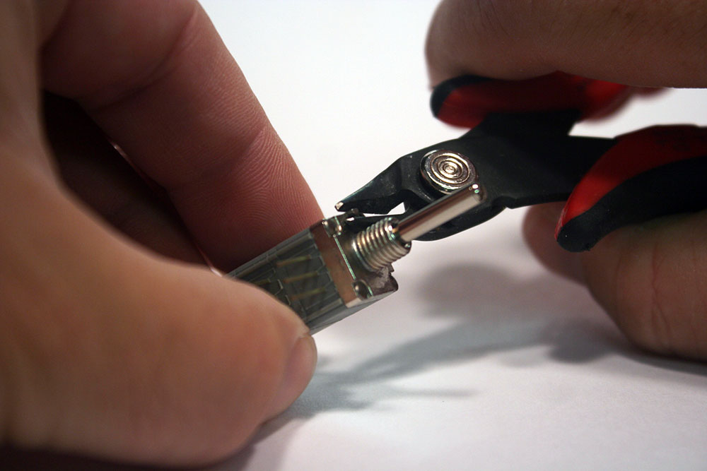
This lug is redundant. It supposed to keep the pot from rotating when you reach the end positions. However, the pot is soldered to the PCB with 9 leads and secured to the front panel with a nut and lock washer. It's not going anywhere.
If you have the current version of the L-bracket, you'll have a 1/8" t-pad hole and a hole for the anti-rotation lug. However, the lug sticks out just slightly past the surface of the L-brack and will prevent the faceplate from mounting flush against the front panel. You need to trim off about 1/3 of the lug so it sits just below the bracket like shown below. Don't worry if you trim off too much or trim it all off. Again, it's pretty redundant. It's like wearing a belt with suspenders.
If you ordered your kit before mid-June 2016, you will have a blue t-pad that has 4 support rails and comes in a plastic package. For the installation of that T-pad, please follow the instructions located on this linked page.
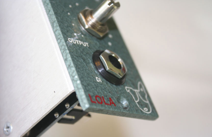
DI Jack
The next component to mount is the Neutrik 1/4” stereo PCB mount jack. Although this is a stereo jack, it’s meant to only receive an unbalanced cable. The extra contact is needed as part of the relay trigger circuit.
The Neutrik DI jack has three parts.
-
The DI Jack
-
The Silver Nut
-
The Black Washer
This part needs to be mounted off the PCB.
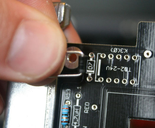
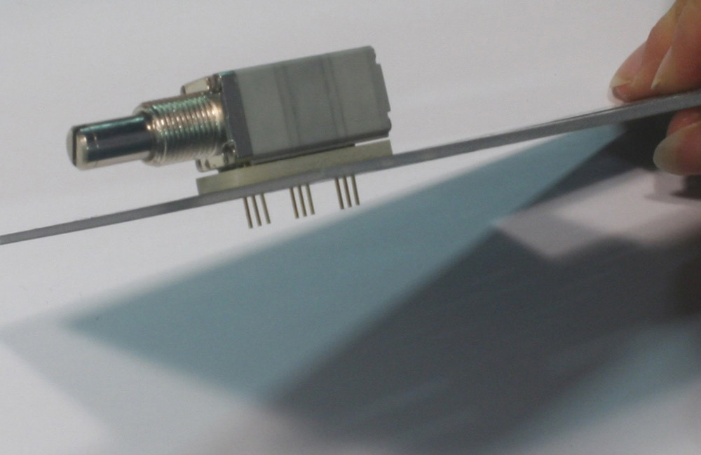
For the DI jack mounting, you are going to need your L-bracket, front panel, Grayhill nut, and washer, (4) #4 nuts, (4) 4-40 1/2” flat screws, and (4) 1/4” standoffs. Mount the 1/2” machine screws and standoffs onto the L-bracket as shown.
Do not tighten the standoffs so they are flush to the bracket. They need to be loose because we’ll need a little wiggle room shortly.
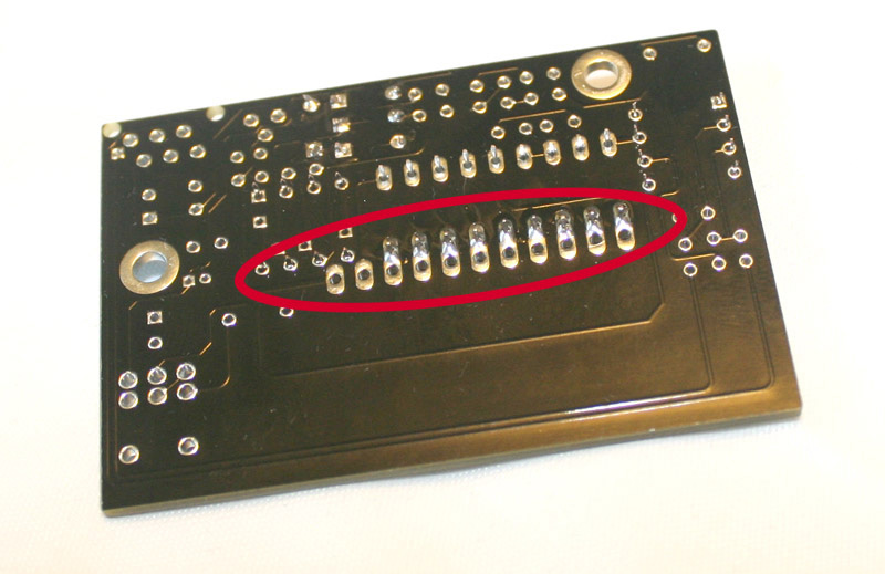
Next insert the jack into the PCB. Now take the PCB and insert it at an angle into the L-bracket. Now place a #4 nut on each screw to set the PCB in place on the bracket. At this point there is no need to use the locking washer or over tighten. Just tighten the screw and nut enough to set the final mounting position.
Now slip the Lola front panel into place and hand tighten the Grayhill nut, attenuator nut, and DI jack mounting hardware.
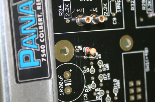
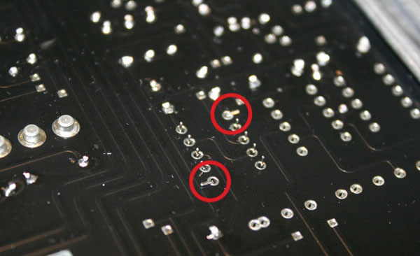
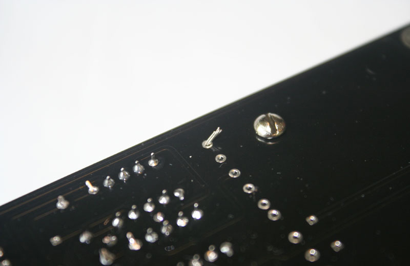
Now that the DI jack is locked into place you can solder the exposed pins on from the top side of the PCB. In this case, the only accessible pins are the three on the PCB edge circled in Red.

You can now remove the front panel and L-bracket and set them aside. We won’t need them for a while. Be sure to place you Grayhill switch, attenuator, and DI jack nuts and washers in a safe place. The safest place is probably on the component shafts!
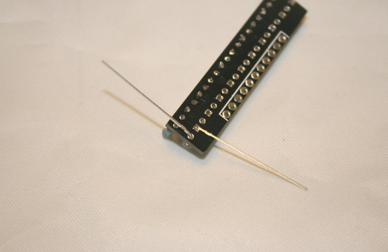
Your DI jack will not be fully stable. Because only one side it soldered it’ll move a little on the unsoldered side. We want to solder all the pins in place but also ensure it stays perfectly parallel to the PCB. If you have a little spacer to use between the jack and the PCB, use it! If not here’s how I do it.
Load a little solder on your iron tip. You know, exactly like they tell you NOT to do. Hold the PCB in one hand and use a finger on that same hand to hold the jack parallel to the PCB.
While holding it in place turn the PCB over and place your solder blobbed tip to one of the unsoldered leads. Yes, that right, make a cold solder joint. Don’t worry, we’re going to fix this. This is just temporary. Before properly soldering the remaining 2 pins on the unsoldered side, confirm your jack is parallel to the PCB. If it’s off, fix it now while you only have one pin tacked in place. Once all the pins are soldered, it’ll be a pain to fix. If it looks good, go ahead and solder the 2 remaining pins properly. Once they are done go back and reheat and solder the tacked joint. You should also solder the three top soldered pins on the outer edge from the bottom at this point.
Looks good? Congratulations! Mounting the attenuator and DI jack is probably the most technical part of the build.
Gain Capacitor
This is that large polarized 1000uF/50V electrolytic capacitor we set aside earlier. It’s an insurance policy to eliminate any DC that finds its way into the feedback/gain network. Be sure to mount the capacitor flush to the board and straight to avoid interference with other components.
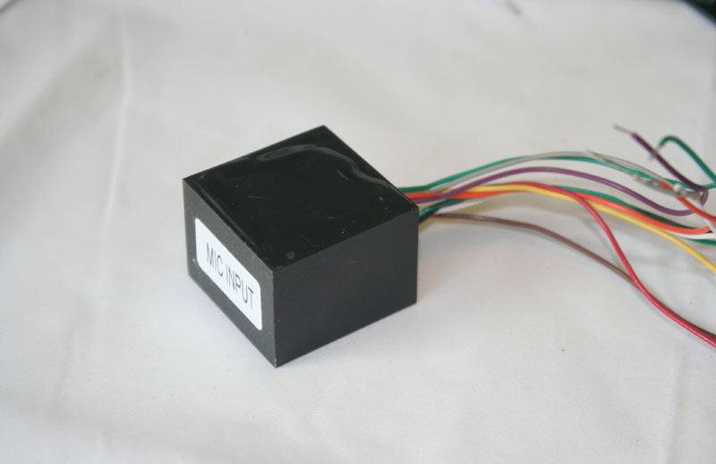
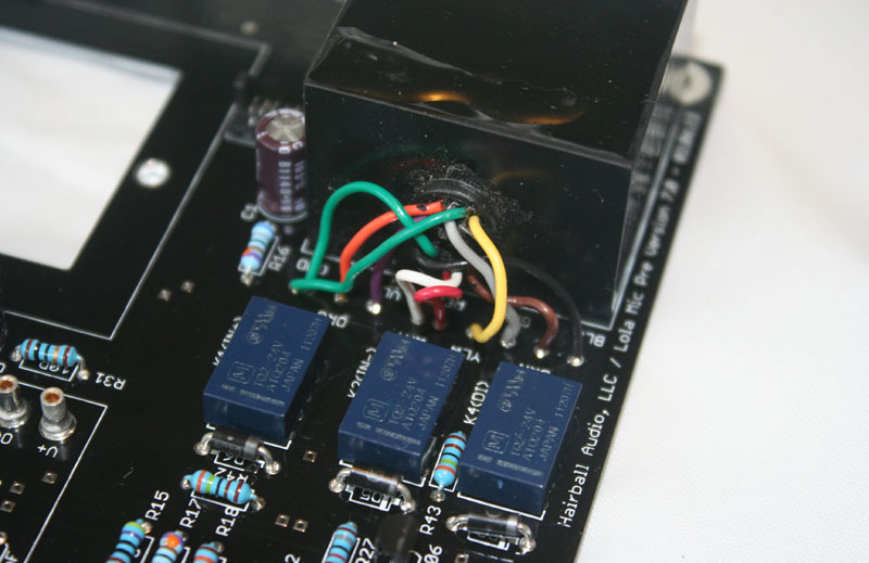
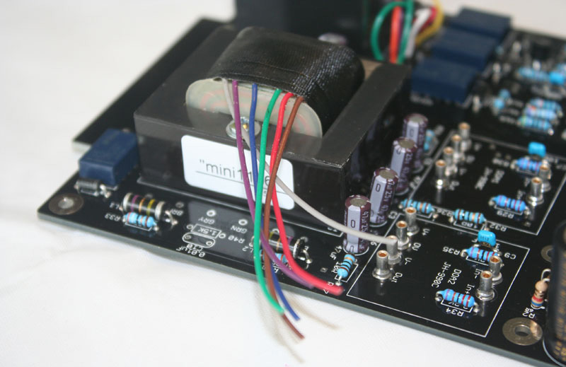
Input Transformer
The Lola uses an EA-10468 input transformer. The EA-10468 is a talented transformer, designer Ed Anderson’s take on the classic Marinair 10468. The 10468 is most known for being the mic input transformer for the classic Neve 1073 channel strips.
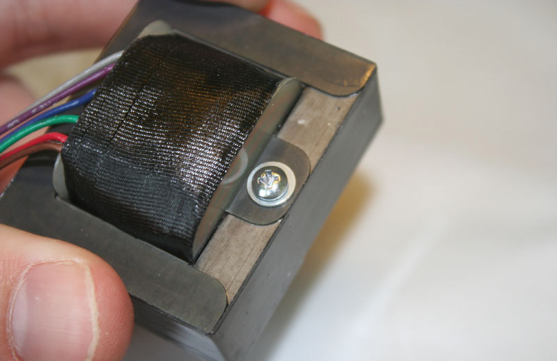
Mount transformer using the supplied (2) 1/2” 4-40 pan head screws from the bottom of the PCB into the threaded holes on the bottom of the transformer. Trim the leads to prepare for soldering. Be very careful not to over trim.
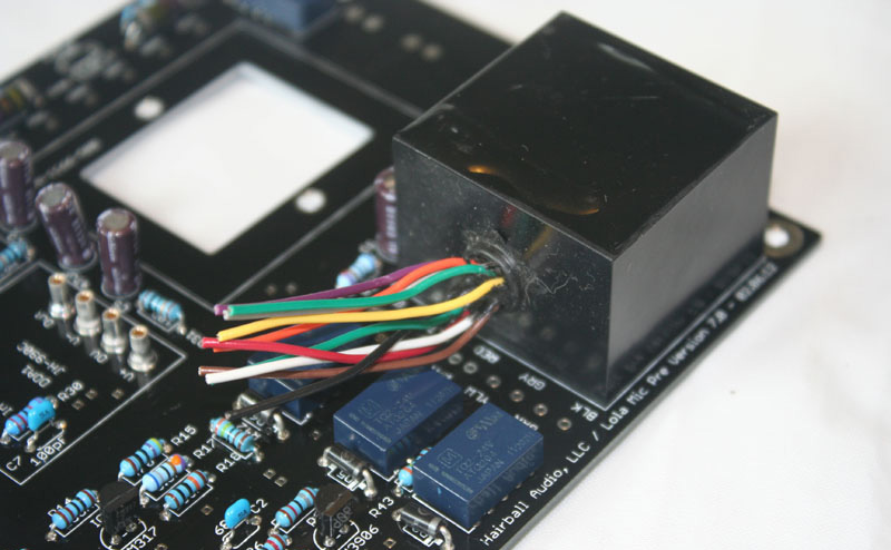
The leads are not hair, they won’t grow back. You can always trim each lead to the perfect length as you solder them into place. The leads have corresponding pads labeled by lead color.
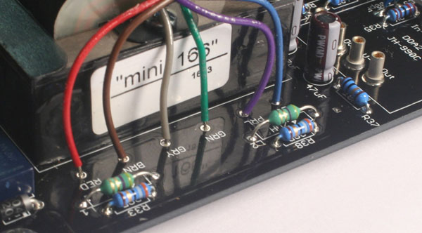
Starting at the board edge and moving towards the center these are:
BLK=Black
BRN=Brown
GRY=Grey
YLW=Yellow
RED=Red (Wow!)
WHT=White
VLT=Violet
ORG=Orange
GND=Green
The GND label is for the two pads that are overlapping. These are the 2 green leads. There are two separate transformer grounds that we are connecting to the ground at this point. It does not matter which green lead goes to which GND pad.
Strip about 1/4” of shielding off the first lead, in this case black, tin the lead, and insert it into the pad with the BLK label.
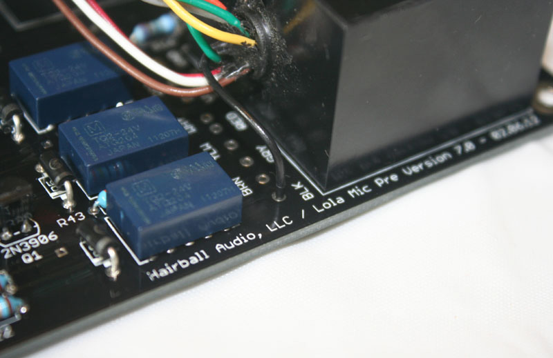
On the bottom side of the PCB. pull the lead through so the cut edge of the wire insulation sits flush with the top side of the PCB. Bend the exposed wire like you would a component lead.
Solder the lead and trim the excess. Now start moving across the board stripping and soldering each lead into place. Make sure you do not leave any exposed wire on the top side of the PCB pads and keep your leads trimmed on the reverse side to avoid any shorts. If you take your time you can probably even make it a little cleaner than I have.
Output Transformer
The output transformer used in the Lola is Ed Anderson’s version of the classic LO-1166 line output transformer.
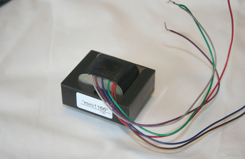
It is used in many designs, most notably the Neve 1073 channel strip.
Let’s start by laying out the hardware we’ll need to mount the transformer to the PCB.
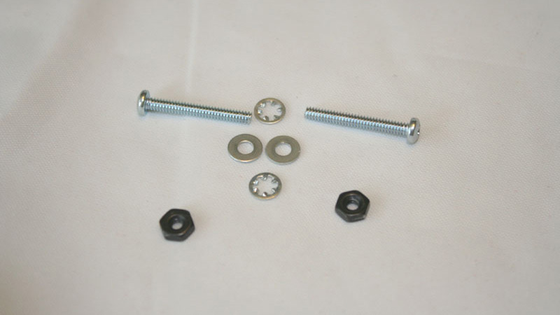
You’ll need (2) 4-40 7/8” pan screws, (2) flat #4 washers, (2) #4 lock washers, and (2) #4 nuts. These are located in hardware bag A. Start by sliding the flat washer onto the screw.
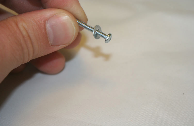
Now do this with the other flat washer and screw and drop them into the transformer holes from the side with the leads on the top side.
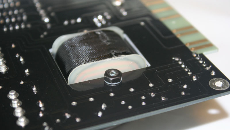
Now drop the transformer onto the PCB with the lead out facing towards the board edge and the transformer solder pads. Flip the PCB over and place a locking washer and nut on each screw to secure the transformer in place.
Now trim your leads. Be careful, it’s very easy to trim these too short. Those solder pads on the edge are further out than you think.
Solder them into place using the input transformer method.
BLU=Blue
PLR=Purple
GRN=Green
GRY=Grey
BRN=Brown
RED=Red
Grab your op-amps of choice and seat them into the op-amp sockets. These are not soldered, they are pressed in so you can swap them out easily. You may have to push pretty hard to get them to snap into place. Apply even pressure so they snap in flat.
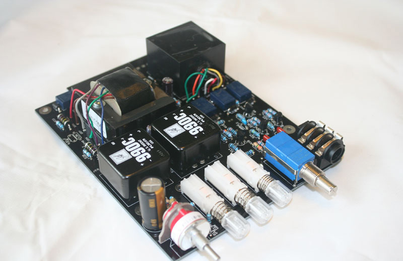
Congratulations! You now have a working Lola!
The mic pre circuit is now fully functional. It’s not a bad idea at this point to test your build. Confirming the main board works correctly can help with troubleshooting should you run into issues when adding the meter daughter board. If you want to test your main board, go ahead and remount the bracket and front panel and skip ahead if you need help mounting the knobs and shaft adaptor.
Testing The Main Board
Let’s get testing! After mounting your Lola in a 500 series rack, power up the rack. Hopefully, you won’t see any smoke. Check the 3 pushbutton LEDs and confirm the light to a nice soft blue. You should hear a relay internally “click” when turning on the PHASE (ø) and LINE push buttons. The PHANTOM (+48) button is not connected to a relay so it won’t have a “click” other than the latching of the pushbutton.
You can use a condenser microphone (not your U47) to test the phantom power and confirm your Lola is passing signal. With the OUTPUT knob fully clockwise, start with the GAIN knob at its lowest setting and confirm your signal increases as you turn it clockwise. Now turn the OUTPUT counterclockwise to confirm the signal decreases to zero.
Now insert a 1/4” unbalanced instrument cable into the DI jack. A relay will “click” but you may not be able to hear it over the sound of the cable insertion. If the instrument you play through the Lola DI jack is amplified you’ll know the relay is flipped. You’ll also know that your Lola passes basic functionality tests!
Populating The Meter PCB
You know what’s awesome? Audio level meters. Let’s give your Lola an awesome LED audio level meter. Start by locating the red “Meter PCB” bag and pull out the contents. Inside you should find five smaller bags. Four are labeled A, B, C, and D and the fifth contains the meter PCB.
Semiconductors
Open meter bag B and locate the four 1N914 diodes.

These diodes are of course polarized and must be inserted in the correct orientation. The line that indicates the cathode on the meter board screen is a bit hidden. Another indicator is the square pad solder pad. The cathode (the side with the line) should be soldered to the square solder pad.
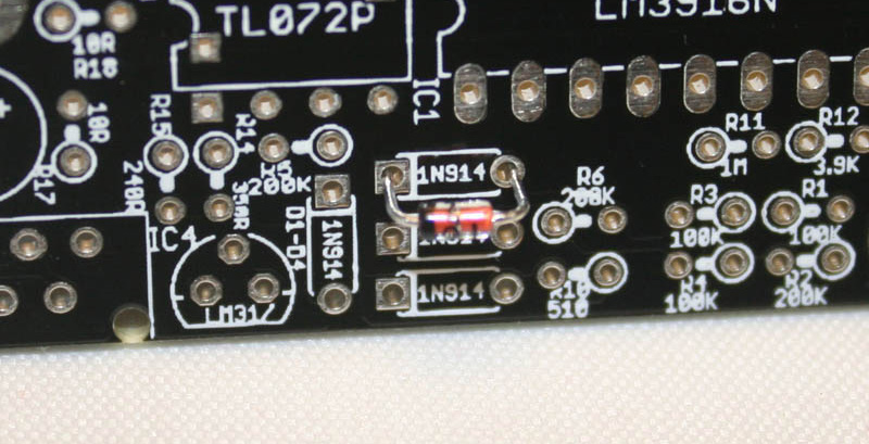
Once you’ve installed all four diodes, install the three integrated circuits.

These can be a bit tricky to install as your board becomes populated so let's get them in there now. The two smaller ICs are labeled TL071CP and TL072CP. Make sure you place these in the correct footprint. They are NOT interchangeable. You’ll notice the larger IC (meter controller) has a notch at one end and the two smaller ICs have a dot at one end. You’ll also notice that the PCB footprints have little notches out of one end. You must align these notch or dots for the IC to be properly installed.
You’ll have to pinch the IC legs in a little to get it to fit into the footprint. You’ll be a pro once you’ve installed about 200 of these.
You’ll notice that one side of the LM3916 pads are joined or bridged to other pads. These 11 pads are for the right angle connector that will attach the LED PCB to the meter PCB.
These 11 pad holes must be kept free of solder until the right angle connector is installed. When soldering the LM3916 make sure you don’t use too much solder or it may flow into these holes. If you’re not confident in your soldering skills, leave this side unsoldered and solder it after the connector is inserted.
Lastly, install the LM317 voltage regulator paying close attention to the silk-screen orientation shape.
Resistors
Next grab meter bag C. It contains all of the resistors required for the meter PCB. Just like the gain resistors, they will be inserted vertically.

Capacitors
Next, install the contents of meter bag A. These are the various capacitors needed for the meter circuit. You have three polarized electrolytic capacitors. Two are labeled 47uF and one is labeled 2.2uF. or 3.3uF. These must be oriented correctly. Again, the negative lead is labeled by a stripe containing a negative or - Symbol on the side. Insert the positive lead with the + symbol on the PCB. The + lead is also the square pad which is opposite to the diode where the cathode or negative is a square pad (don’t ask).
You also have three non-polarized capacitors. These can be inserted in either orientation. You have two 0.22uF (labeled XXXX) capacitors and one 0.47uF (labeled XXXX) capacitor. Insert these into their proper footprints.
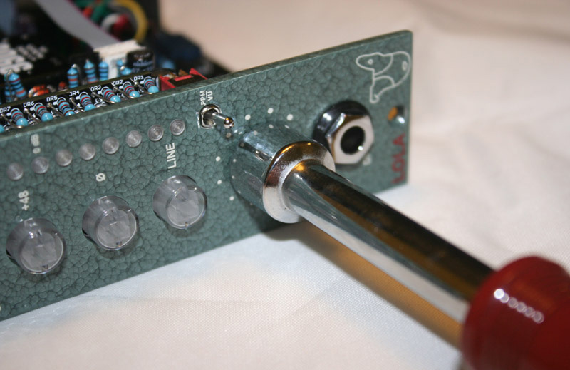
Toggle Switch and Connectors
Finally, you’ll be left with meter bag D. Remove the toggle switch and one of the two small PCB mount ribbon connector headers. Set the rest of the bag aside for now.
Inserting the toggle switch and header are fairly straight forward. The footprint will help you with orientation. All you need to do is make sure they are solder flush to the PCB. It’s best to start by soldering one pin and confirming the part is flush to the PCB before moving on. When you’re done. you should have something that looks like Fig 53.
Remember, your PCB is a newer production version that may look slightly different. For example, the right side of your meter PCB will look slightly different than the one pictured in this manual.
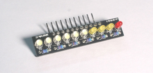
Populating The LED PCB
Congrats, you only have one PCB left to populate and it’s the smallest. Don’t be fooled however, take your time with this one to ensure the LEDs will align properly with the light pipes. Without further adieu, let’s populate the LED PCB!
The LED PCB allows us to mount the LEDs flush to the PCB eliminating the need for any trickery or LED lead bending. It also allows us to have current limiting resistors for LEDs as needed which creates a lot of flexibility for different LEDs and different LED color combinations.
Start by mounting the current limiting resistors. Mount the six 47K resistors into DR1-DR6.
Next, we’ll mount the LEDs. Try not to mix them up! You want these to sit as flush and as straight to the PCB as you can get them. It’s not 100% critical that they are perfect, just take your time and get them close.
The longer lead is the anode (positive) and should be inserted into the square pad...which is opposite to the diodes...again, don’t ask.
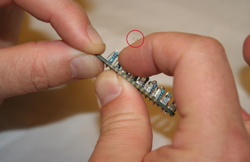
I like to hold the PCB with one hand and insert the LED with the other. Press the LED close to the board with your index finger and use your thumb to spread the leads apart bending them against the PCB.
You have a fleshy chunk of skin hanging off your cuticle (circled in red), now would be the time to trim that off with nail clippers or your wire cutters.
Note that the LEDs footprints are labeled W for white, Y for yellow, and R for red.
When you flip the board you should see something like below. Solder the LED into place and clip the leads.
Continue along down the line. Note that the top red/violet LED solder pads will back up close to the meter board 0.22uF caps once it’s installed. To keep things tidy don’t put a big glob of solder here (or anywhere) and clip the leads very short after soldering.
Next, let’s mount that right-angle connector. It mounts to the opposite side of the PCB than the LEDs and resistors. This is yet another component that must be mounted flush and straight. It’s not difficult at all, just take your time and solder one or two pads then double-check that they are still flush to the PCB. I find that if you orient the part as shown below and solder it in place using some downward force with the iron you can get it just right.
Note the smaller leads on the right angle connector are soldered to the LED PCB and the longer leads will be soldered to the meter PCB.
Let’s finish this off! Grab the meter PCB and insert the LED PCB so the LED face the same side as the toggle switch. As you may have guessed, it’s important the LED PCB sits flush and at a 90-degree angle to the meter PCB.
Flip the board and solder the right angle connector into place. Again, confirm the LED PCB is flush and straight after the first few pads are soldered.
Flip the PCB and trim the long leads of the connector. When you trim these leads place your hand over them as a shield or hold them as they are clipped. These leads fly far and fast when they are cut.
Now let’s take a moment to survey our work.
Congratulations! All of the electronics work is done! All that’s left is the final assembly.
Putting It All Together
We’ve reached the point where we finally get to put it all together. Most of this is fairly straight forward, as always take your time. Rushing through this is a great way to strip a screw or add a hideous scratch to your build.
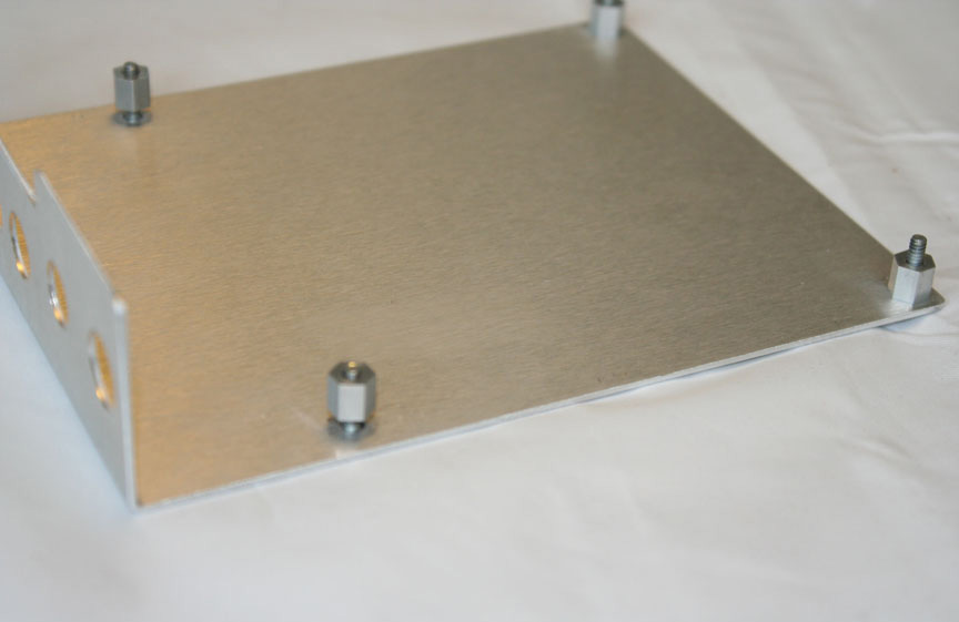
Mounting The LED PCB
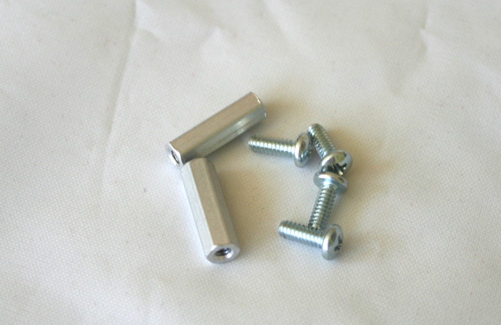
Grab the hardware bag and locate bag A. Carefully empty the contents onto your workbench (aka dining room table) and Grab four 5/16” 4-40 pan screws and two 5/8” #4 standoffs.
Locate the two large holes near the pushbutton switches and feed two of the pan head screws through the bottom of the PCB. Now take the standoffs and thread them over the screw shafts and tighten them.
Now place the meter PCB over the standoffs and use the two remaining screws to screw it into place.

Do not tighten these top screws until you have the bracket and front panel in place.
Inserting The LED Light Pipes
Get out that sexy front panel!
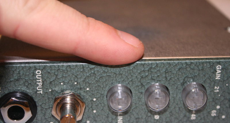
Grab bag B and VERY carefully remove the contents. The light pipes are not easy to find if dropped on the floor. so be careful. You should find 10 clear light pipes and 10 black rubber retainers.
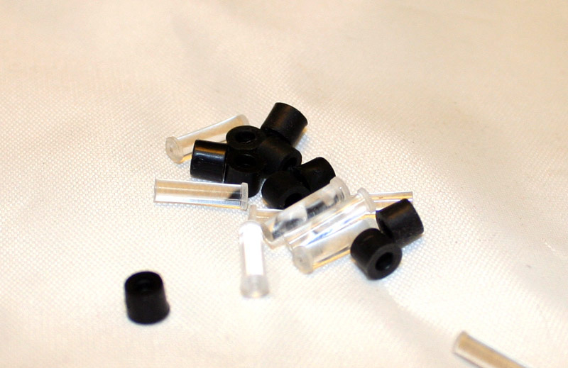
Insert the shaft of the light pipe through the front on the front panel. Pressing your index finger against the top of the light pipe, slip the retaining ring over the light pipe shaft. Once you have all of the light pipes and retainers installed, tighten the fit on each retainer by holding the light pipe tight with your index finger and sliding the retainer down tight with the edge of a pair of needle-nose pliers. Don’t squeeze the retainer or pipe with the pliers. Just use the edge to push it toward the back of the front panel.
Mounting the PCB to the Bracket
By now you’ve done this a few times. The only difference is that this time use a #4 lock washer located in bag A on each of the mounting screws before tightening the #4 nut.
The Ribbon Connector
In the meter bag D you have a ribbon connector. The ribbon connector is polarized in that one side of the PCB header has a thin vertical tab, and the other has a thick vertical tab. If you look at the side of the connector you’ll see a thin slot and a thick slot. Line up the tabs and press the cable into place at the meter and at the main PCB between the transformers.

Mounting The Front Panel
Dig out the DI nut and washer as well as the nut and lock washer for the t-pad and Grayhill switch. Mount the front panel and loosely screw the nuts and washers into place. Align the front panel by running your finger along the edge of the front panel and rear of the L-bracket.
Now tighten all three nuts with a nut driver or tool of choice.
The required nut drivers are:
DI Jack - 7/16”
Output T-Pad - 1/2”
Gain Grayhill Switch 5/16”
DO NOT overtighten these! You're not putting a wing on an airplane. Just hand tighten, then twist one more 1/2 turn with the nut driver.
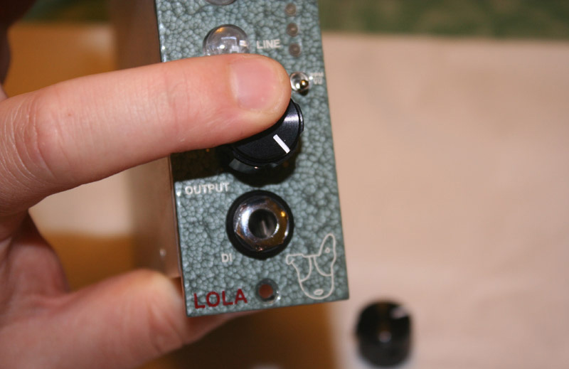
Mounting the Knobs
This is it, the last step. Let’s wipe the tears from our eyes and get this done. Open up hardware bag C and grab the two knobs. The 1/16” hex wrench is not included but you’ll need one for this step.
Mounting the output knobs is straight forward. Rotate the output knob fully clockwise. Each knob has two set screws. Loosen both with your hex wrench so the knob will filly slide over the output t-pad shaft. Align the white line with the last large dot in the fully clock wide position and tighten both set screws.
Rotating the Grayhill switch to the fully clockwise position. You may need to do his with a pair of needle-nose pliers to get the necessary torque and grip. Your Grayhill shaft should resemble the positioning below.
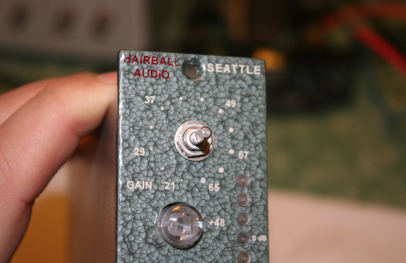
Finally, slip the knob over and align the white line with the 65db dot and tighten both set screws.
Lastly, step back and admire your work. You’re done!
Final Testing
Depending on your level of expertise and available equipment, there is a wide variety of tests you can run. I’ll guide you through a few basic test points.
Run the tests from the Testing The Main PCB section.
Feed a signal through Lola and adjust the input and output so you are getting +4dBu (1.25V) at the output. You’ll need to figure out the best way to do this based on your available equipment. With a +4dBu output, your LED meter should light to the first orange LED in VU mode. Switch output to +1dBu (0.869V) output and the meter should light to fifth LED in VU mode. With the same output level switch to PPM mode (0.869V = 1.25V Peak) and the meter should light to the first orange light (0dB).