Bill of Materials The Bill of Materials (BOM) is a list of all the components and hardware needed to complete your build. It includes information like component values and location designations. If you have not done so already, click the link below to access the FET/500 BOM and build map for your Revision.
Revision A V2.X and Lower
Revision A V3.0 and Higher
*These 2 versions of the Rev A use R-OPT in very different ways. Before V 3.0 (located near Q1) it should ALWAYS be a short. With V3.0 or later (located near the input pot) it should be left empty or be stuffed with a 100Ω resistor if using the input mod.
Revision D
Revision F
Meter Board
Note: When reading the BOM leading zeros are used for sorting purposes. Ignore all leading zeros.
Example:
R002 = R2 on PCB
R020 = R20 on PCB
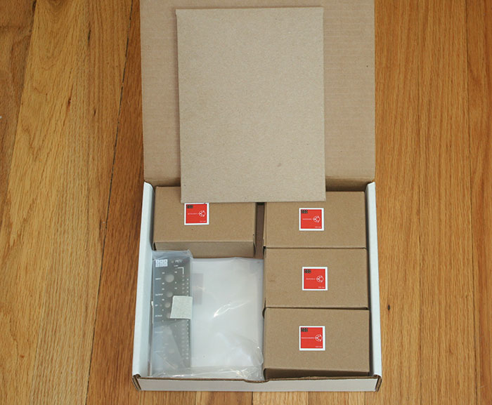
All the parts listed in the BOM will be included in your kit. The kits include the following boxes:
Revision Kit: This box is labeled either Rev A, Rev D, or Rev F. It includes the components used for your particular revision build.
Meter Kit: This box includes all parts needed to build the meter PCB.
Hardware: This box includes all hardware needed to mount the PCB and output transformer.
Transformers: This box contains the input and output transformers for your build.
PCB Envelope This includes your main and meter PCB, an L-bracket, and aluminum faceplate.
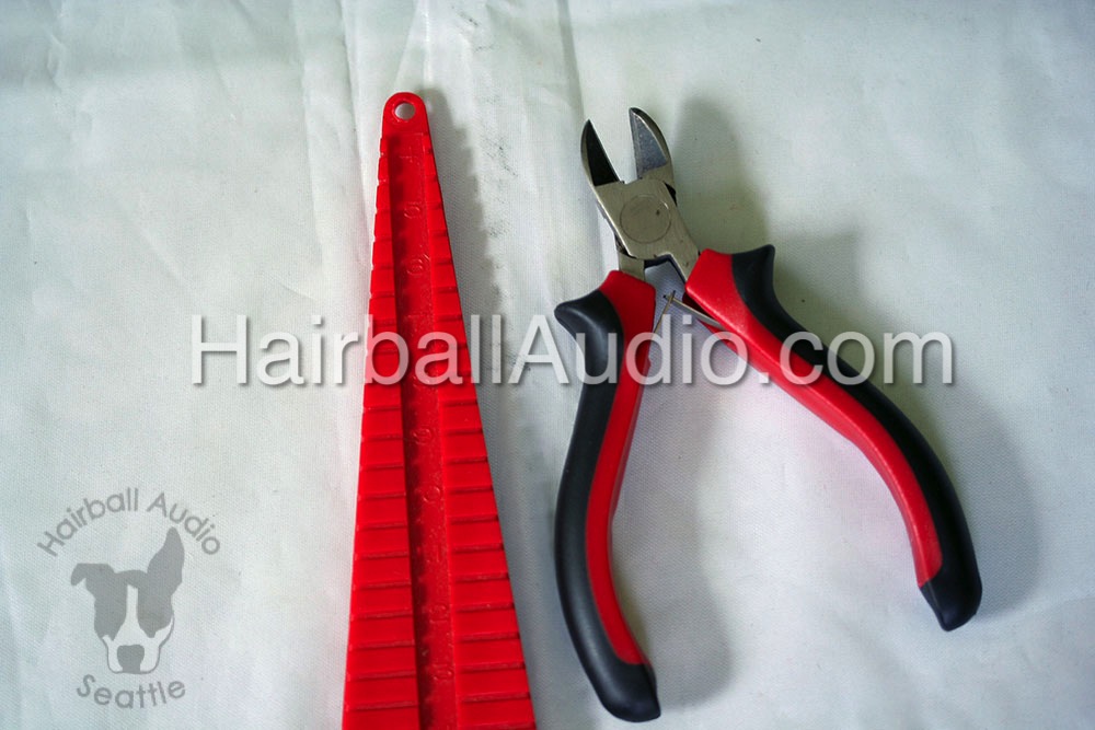
In addition to the BOM and components, you'll want to grab your soldering iron, solder, digital multimeter (DMM), lead trimmers, and a lead forming tool or needle-nose pliers. The lead forming tool shown below is Mouser part 5166-801, but a pair of needle-nose pliers will work just as well.
Before You Begin
Before you start, make sure you have the proper PCB for your build (we make mistakes).
Revision A: Blue PCBs
Revision D: Black PCBs
Revision F: Red PCBs
It will also help your build go smoothly if you read through this complete guide before you begin. In addition, look over your kit and see if you are missing any components.
Resistors
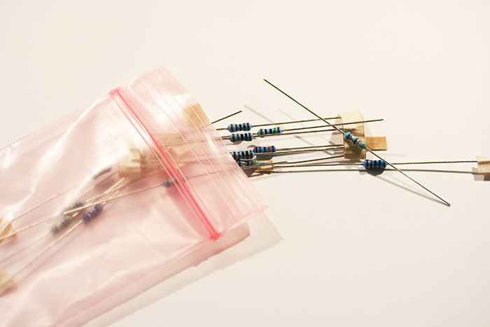
Components are generally stuffed from shortest to tallest for easiest assembly. Let's start with resistors since they are small and account for many of the on-board components. Take your time, soldering resistors is easy, but misplacing a 270Ω for a 270KΩ resistor is not an easy thing to sort out when your build doesn’t work right. Test each resistor with your DMM resistance (Ω) setting before soldering it in place. You'll rest easy later on.

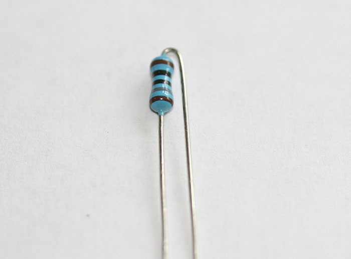
I know my resistor color band codes, but I’ve checked this 150KΩ resistor anyway. Not only have I double-checked with my eyes, but I’ve also confirmed it’s working correctly. Resistors are not polarized. You can insert them in either direction. Take your time (really, please TAKE YOUR TIME), the extra time now can save you hours or days of troubleshooting.

When inserting resistors, it's good practice to mount the resistors color codes in the same direction. Meaning all of the color codes would read right to left or up to down. This is not necessary and does not affect your builds performance, however, it will make things a lot easier if you have an issue and need to go back and confirm the resistor values by reading the color codes. When installing components, bend the leads at a 45-degree angle to keep it in place.
Leads bend after inserting. If the leads are long, trim them shorter to avoid the long leads acting like a heat sink.
After soldering, trim the leads down to the solder. Notice how we didn't use a ton of solder. Less is more! Some resistors in the Revision A and Revision D side-chain are vertically mounted. This is done when space is limited. To mount these resistors, take your finger and bend one of the leads over into a J shape.
Bent Resistor. Try not to bend too close to the body. These resistors are installed vertically. One of the pads will have a circle around it. This indicates that this is the pad in which the unbent lead should be inserted and where the body touches the PCB. This has nothing to do with polarity or circuit functionality, the resistors are arranged in a particular way to avoid having bent leads touch each other and create unwanted shorts.
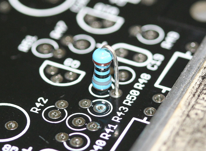
Vertical resistor installed with the resistor body inside the silkscreen circle.
REV A NOTE: On all PCBs before V3.0 ROPT1 is located near Q1 and should always be a short. You must insert a wire jumper here and short that space. You can simply use a clipped resistor leg and solder it directly across. For V3.0 or later R-OPT is located near the T-pad and is for the input mod to tame the input. This needs to be left empty (no mod) or stuffed with a 100Ω resistor (modded). The 100Ω resistor is not supplied.
Diodes
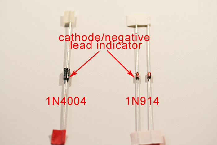
Diodes are next. They are bent and soldered like resistors however, there is one major difference: DIODES ARE POLARIZED DEVICES.
Components that are polarized have a positive and negative lead which must be inserted into the correct pads on the PCB. These leads are the Anode (+) and cathode (-).
There are 4 diodes used in the FET/500 series main and meter PCB. There are 1N914, 1N4740, FDH333, and 1N4004. Your diode will have its name printed on the diode itself. Look really close! On your diode, you will notice one lead is marked with a line. This line identifies the negative or cathode lead. The silkscreen also shows the diode with a line at one side which indicates how the diode should be inserted. Pretty easy!
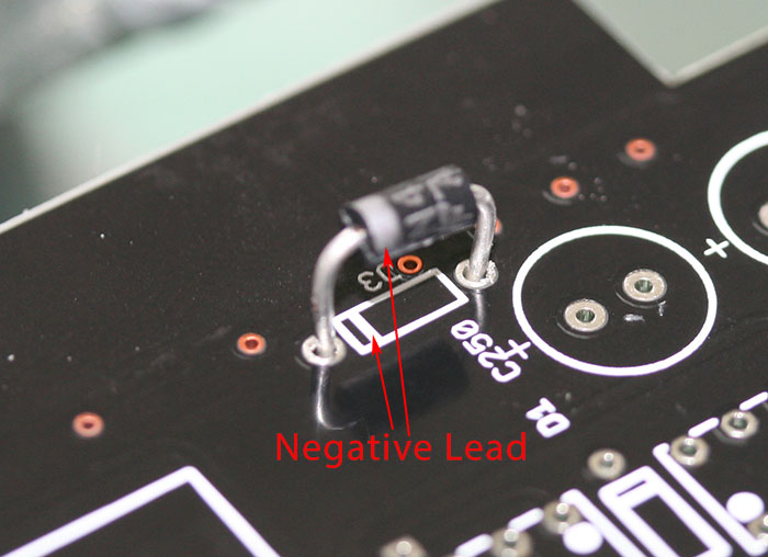
Notice how the lines align.
Transistors
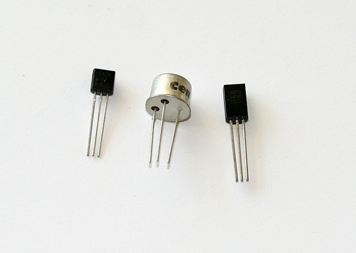
Transistor found in the FET/500. L-R: TO92, TO39, TO266 (Rev F Only). We could go a few different directions at this point, but let's move to transistors. There are many that look the same, they're not!

Most of the transistors are TO-92 types. The most notable, is the 2N5457 matched Field Effect Transistors (F.E.T.). These two transistors are what makes this circuit a F.E.T. compressor. Q1 controls the gain reduction, and Q11 (Q10 on the Rev F) matched the GR meter to that FET. If you've purchased a stereo set, you'll have one bag marked Q1 and one marked Q11 (Q10 for Rev F) each with two transistors. Use the Q1 transistors for the Q1 position in each unit and the Q11 transistors for the Q11 position in each unit.
The Revision A also includes two J309 FETs. These are used on the gain stages and are part of what gives the Revision A its unique sound. FETs have three leads: Source, Drain, and Gate.
The rest of the TO-92 transistors are bipolar junction transistors (BJTs) and the three leads as well: Collector, Emitter, and Base. To make it easy for you, the PCB silk-screen for all of the TO-92 transistors (FET and BJT) matches the package of the transistors. Identifying the transistors is easy, their names are marked on their bodies.
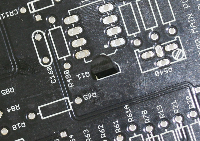
Above shows a TO-92 inserted. The Revision F includes two larger TO-266 type transistors. These are used to drive the push-pull output. They look identical, but one is a PNP and the other is an NPN. One is active for the positive swing of the audio wave (NPN) and the other is active for the negative wave (PNP). The NPN is Q8 and is the transistor labeled MPSW06. The PNP is Q9 and is the transistor labeled MPSW56. The Revision A and D circuits use a class A output. So rather than the two transistors used in the Revision F, they use a single T0-39 transistor.
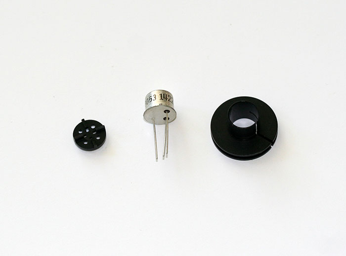
Parts in the Q6 assembly (Rev A and D only). L-R: spacer, TO-39 transistor, heat-sink. This transistor is a 2N3053 and is a BJT. It comes with a couple of accessories. It has a spacer, which will help keep it from buckling when adding the next accessory, the heat-sink. This is a class A circuit and this transistor (Q6) gets HOT. It needs this heat-sink and be aware of it when pulling the module from the rack. That heat-sink can easily burn your hand. Insert the transistor by aligning the tab on the transistor with the tab on the silkscreen. The tab is what identifies the emitter, with the collector being furthest from the tab. Place the spacer underneath the transistor and mount it tight to the PCB. Press the heat-sink over the top of the transistor head.
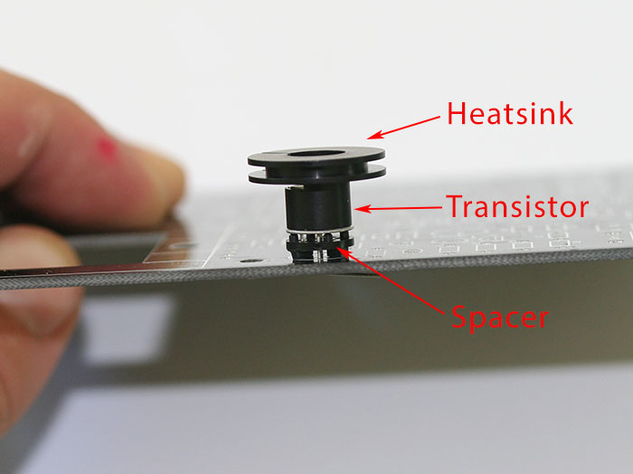
Mounted Q6 (Rev A and D only).
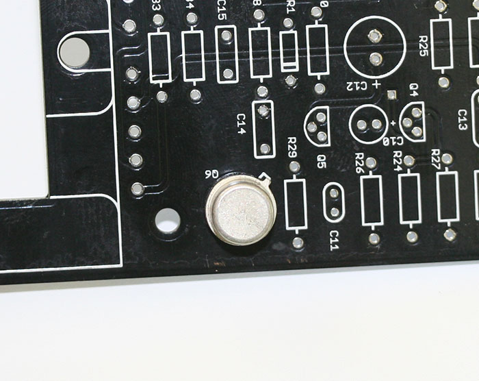
Top view with heat-sink removed.
The meter PCB includes two LM317. These look like transistors because they are in a TO-92 package, but they are not transistors. They are voltage regulators. You can learn more about these devices online, but for the sake of this build, they are inserted just like the TO-92 transistors.
Capacitors
Let’s talk capacitors! The images that follow cover the types found in FET/500.
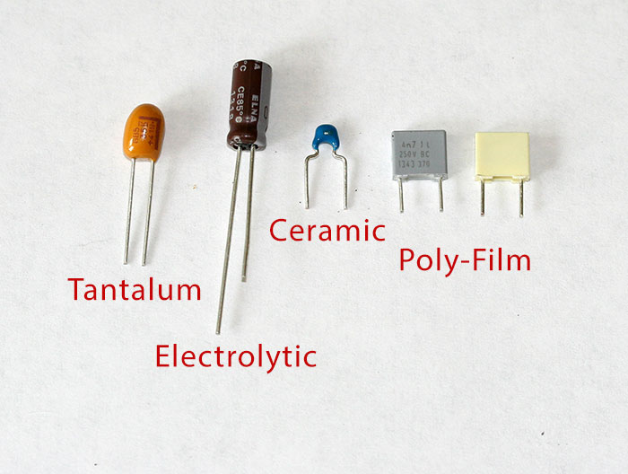
These are the basic types of capacitors in your kit. Let's start by installing the film, ceramic, and mica (not pictured) capacitors. These are the ONLY capacitors in the kit that are non-polarized, meaning they can be inserted in either direction. The ceramic capacitors are small and blue. If you do not have a DMM that reads capacitance (farads), you can read the value on the capacitor body (look close!). The first two numbers are the first two numbers of the value, and the third number indicates the number of zeros you add to the end. There may or may not be a letter at the end that indicates tolerance.
270 = 27 pF
271 = 270 pF
104 = 100000 pF or 0.1uF.
The mica capacitors are black, brown, or yellow. There is one 6.8pF mica cap in the Rev A build and two 200pF mica caps in the Rev D/F build.
Next, we'll install the film caps. There are two types: grey Vishay and cream Kemet. The cream Kemet caps are used in any position in the circuit where a film cap is used to couple two stages of the circuit. This makes them important, and we've selected these because we like what the do for the overall sound of the circuit.
The cream Kemet caps are used in the following positions:
Revision A: C1, C2, C8 (0.15uF)
Revision D: C1 (1uF), C8 (0.15uF)
Revision F: C1, C10 (1uF)
All other film positions use the grey Vishay caps. If you don't have a DMM that reads capacitance (farads), you can read the value on the body. Depending on the brand and value, the capacitance might be displayed in uF, nF, or pF (rarely). To convert, simply move the decimals 3 places to the right as you move from uF to nF to pF.
0.0001 uF = 0.1 nF = 100pF
A calculator is available here: http://www.calculator.org/property.aspx?name=capacitance
Note that a value listed as 4n7 means 4.7 nF or 4700 pF.
Polarized Capacitors
All of the electrolytic and tantalum caps we'll be using are polarized. Meaning they must have a positive (+) and negative (-) lead that must be installed correctly. The negative lead is marked with a "-" and an arrow pointing to the lead. In addition, the positive lead is longer. On the PCB the positive pad is marked with a "+". Start by inserting the power supply filter caps.
There a couple of types of 100uF capacitors in your kit, Nichicon HE and United Chemi-Con KZE series. The Nichicon HE capacitors are used for the filter capacitors. You can read the brand and values on the body of the capacitors.
These filter caps are:
Rev A - C2500, C2500
Rev D - C250, C260
Rev F - C25, C26
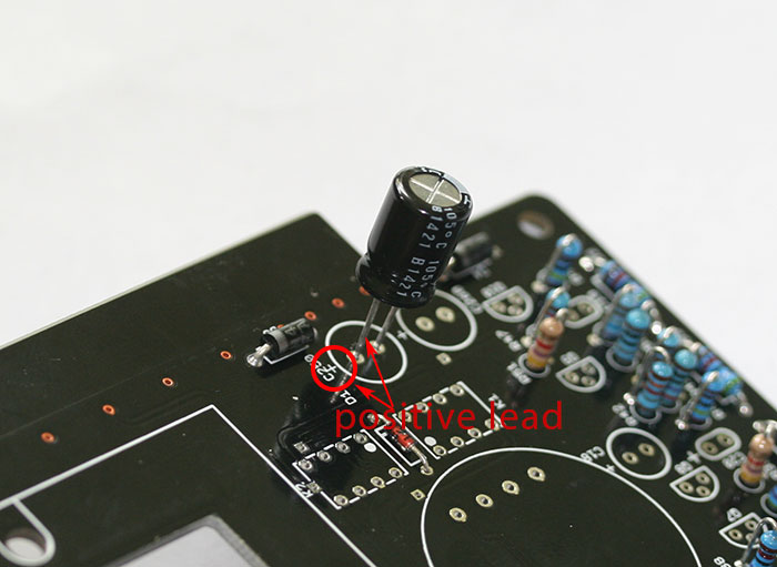
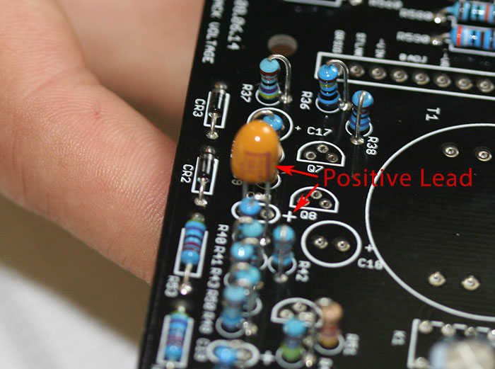
Nichicon HE being inserted. Note the polarity. For the rest of the 100uF caps, you'll use the United Chemi-Con KZE caps. Depending on the revision you are building, you'll have a mix of Chemi-Con KZE, Panasonic FC, and Nichicon PW electrolytic caps left. Simply follow the BOM to see where the caps are placed. Note the polarity when inserting these caps. Tantalum caps are polarized as well. Their positive lead is marked with a "+" and a line pointing to it. All revisions include two 6.8uF tantalum caps in the side-chain. For all revisions, these are C19 and C20.
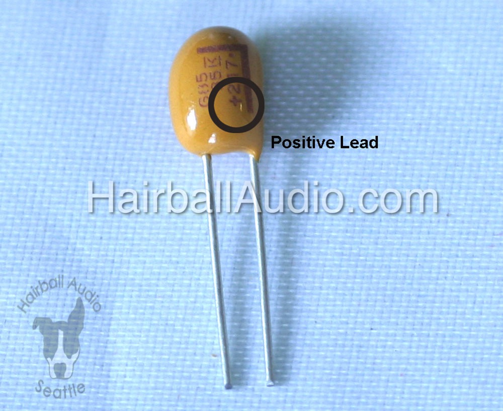
Tantalum with the positive lead identified.
LEDs
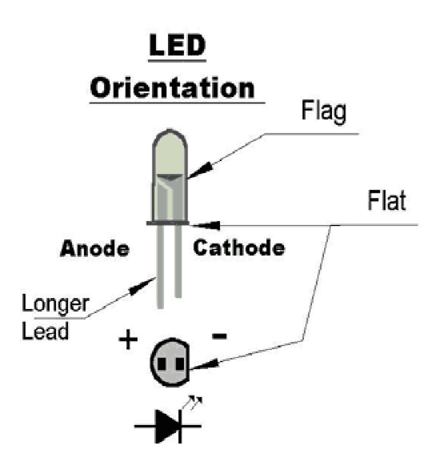
There are a number of Light light-emitting diodes (LEDs) used in the FET/500 project. Two are on the main PCB and 21 are used on the meter PCB. The two on the main PCB should be mounted before the pushbutton switches.
The long lead is positive and the flat side of the LED ridge is aligned with the negative lead. On the PCB the negative pad has an arrow pointing towards it with the cathode line slowest to it.
For all older versions BEFORE 3.0 (labeled on the main PCB) the LEDs are surface mounted. These versions are labeled with a date. If you have one of these older versions (what took you so long to build your kit?), please follow the SMD LED mounting guide.
Through-Hole Mounting (PCB Versions V3.0 and Later)
You will be bending these LEDs at a right angle. Start by determining the direction of the bend.

Here the long lead is lined up with the positive pad and we'll be bending down towards the PCB.
The meter PCBs have a bending jig built into the meter PCB. Simply drop the LED into the cutout paying attention to match the lead lengths then bend down at a right angle.

Depending on the version of your PCB and the size of the plated through-hole, the LED may slide down and sit flush, or get stuck at the flat area. If it gets stuck, pull on the leads with your pliers and push down with your thumb and the LED will snap into place.

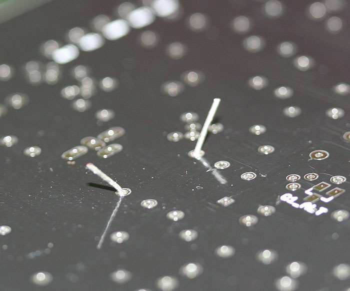
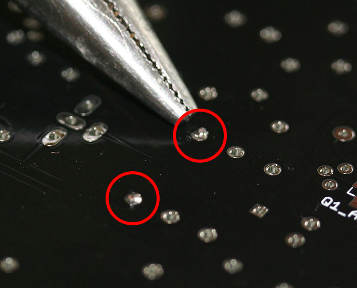
The two leads circled below are stuck at the flat part of the LED lead. The front panel will never sit correctly. You need to pull these through with pliers so the LED leads are flat to the PCB and the LED hangs over the edge of the PCB like the others. DO NOT SOLDER THEM YET.

As you place the LEDs you can trim the leads short. With the link jack in place, use the faceplate to confirm the LEDs are centered and aligned. For best results, do not solder the LEDs in place until you have assembled the whole unit. Then you can top solder the LEDs while the faceplate holds them aligned as shown below.

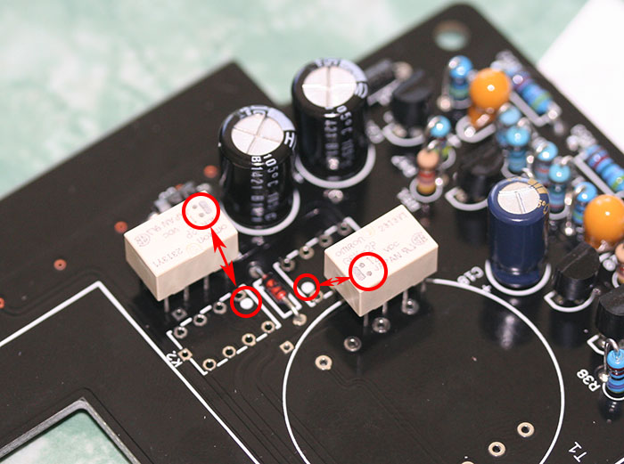
Relays
There are two relays that control the true bypass and they need to be inserted correctly. If you look at the silkscreen you'll see that one corner of the relay screen has a dot. Simply align the two dots on the relay with this dot.
Dip-8 and DIP16 ICs
The main PCB has an integrated circuit (IC) that has 8 leads, 4 on either side (DIP-8). The meter PCB has two DIP-8 and two DIP-16 (16 leads/8 on each side) ICs. The IC name is on the IC body. DO NOT mix up the TL071 (main PCB) and TL072 (meter PCB) ICs, they are not interchangeable. These must be installed correctly and in the correct location. The silk-screen has a semicircle on one end. Your IC will either have the same semicircle or a dot. Insert the IC so the semicircles align or the dot is on the same side as the semicircle.
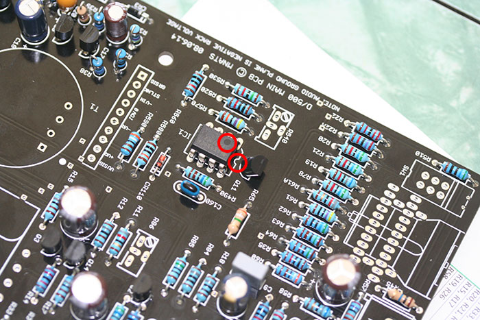
Notice the dot is on the same end as the semi-circle on the silkscreen.
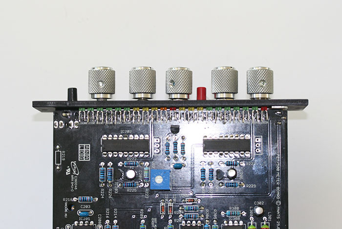
Trimpots
There are 3 styles of trimpots used in the FET/500 build. The style type is a 4 digit code on the trimpot. The 3386 type is the flat square trimpot with the white plastic screw trimmer. There are two and they are used on the meter PCB for hight reasons. The 3266 are the smaller tall type and they have a side adjust trimmer. There are two and one is used on the main PCB as the Qbias trimmer and the other is used on the meter PCB for zero adjust. Note the meter zero adjust is mounted on the bottom of the PCB. The last is the larger 3296 has a top-adjust trimmer. There are two of these on the main Rev A PCB and three on the main Rev D and Rev F PCBs. Their values are indicated on the trimmers with a three-digit number. The first two numbers are the value, and the next indicates the number of zeros.
101 = 100Ω
202 = 2K Ω
103 = 10K Ω
104= 100K Ω
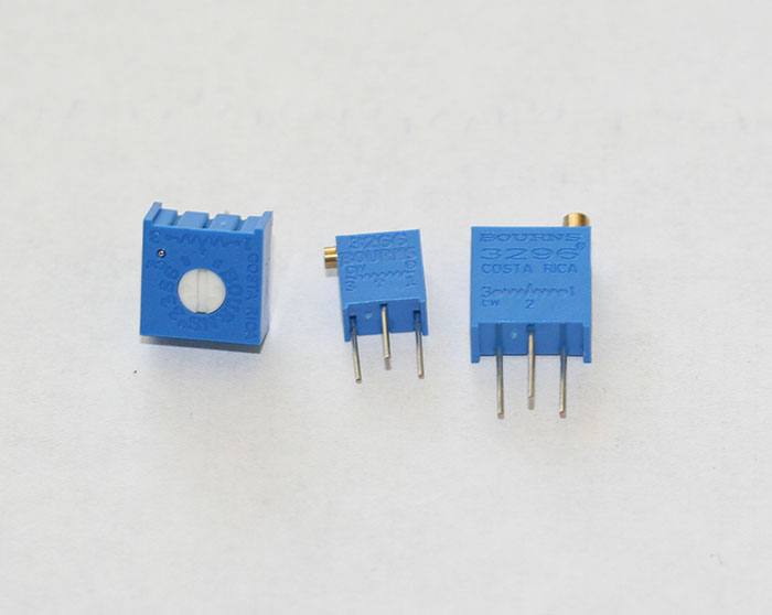
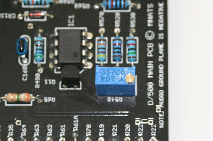
FET/500 Trimpots L-R: 3386, 3266, and 3296. You can also test them with your DMM by setting it to read resistance (Ω) and clipping your leads to the two outer leads. This will give you the total resistance regardless of the trimmer position. For ease of calibration, we recommend setting the trimmers to the midway position. For the 3386 type this is easy to do since they have a single rotation and stops (like a potentiometer). However, the 3266 and 3296 types rotate multiple times and do not have a stop (if you listen closely they "click" when they reach the end). To set them mid-way set your DMM to read resistance (Ω) and place a lead on the middle lead and one of the outer leads. Then rotate the trimmer until your DMM reads 1/2 of the total resistance. For example the 2K would read 1K.

2KΩ trimmer is shown set to the center position.
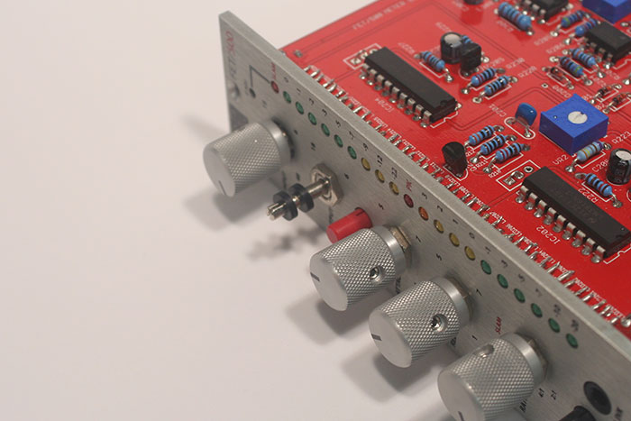
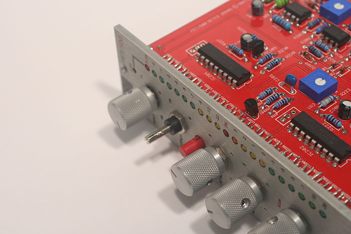
Frontpanel Controls Switches
There are two push button switches included with your kit. One is for the bypass (SW3/red cap) and the other is the Gain Reduction OFF (SW1/black cap). The bypass completely bypasses the compressor. The GR OFF turns off the gain reduction but still passes the signal through the amplifier stages of the unit. Simply press them into place and solder them so they fit tight to the PCB.
Pots/Grayhill Switches
The ratio switch is a two-deck, six-position Grayhill. Before installing the Grayhill you need to install the two graphite stops. With the mounting pins facing down, the stops are at the 12 and 6 o'clock position. It will help with knob mounting if you insert the pins with the flat of the shaft pointing the 7 o'clock position as pictured. Once the stops are fully inserted, place the retaining sticker over the shaft.
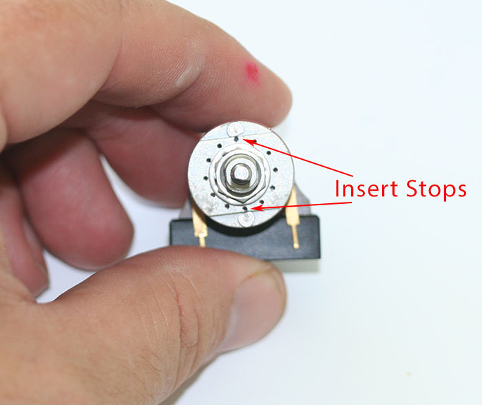
Stop and shaft position shown above.
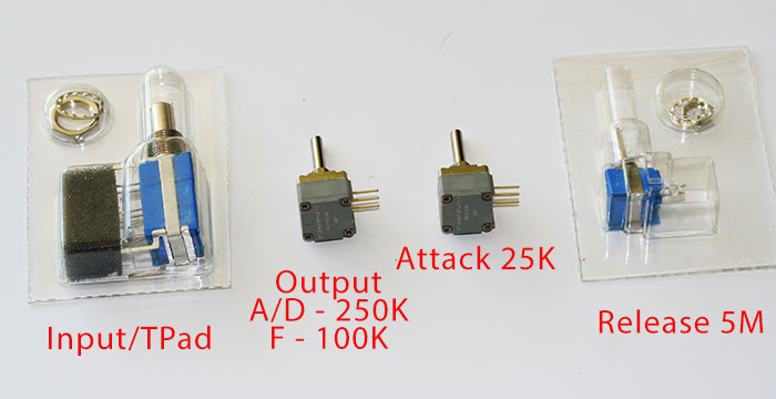
Potentiometers and T-pad
The T-pad is the input control and it is the 3-deck pot. The output is 250K for the Rev A/D and 100K for the Rev F. The attack is 25K and the release is the 5M ohm pot. The values are written on the rear or top of the pot. Important: any grey pots have anti-rotation lugs that stick out slightly past the surface of the L-brack. This will cause your pots to sit slanted when the nut is tightened. You need to trim off about 1/3 of the lug so it sits just below the bracket. Don't worry if you trim off too much or trim it all off. They are pretty redundant. It's like wearing a belt with suspenders.
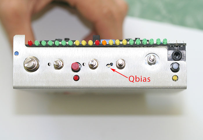
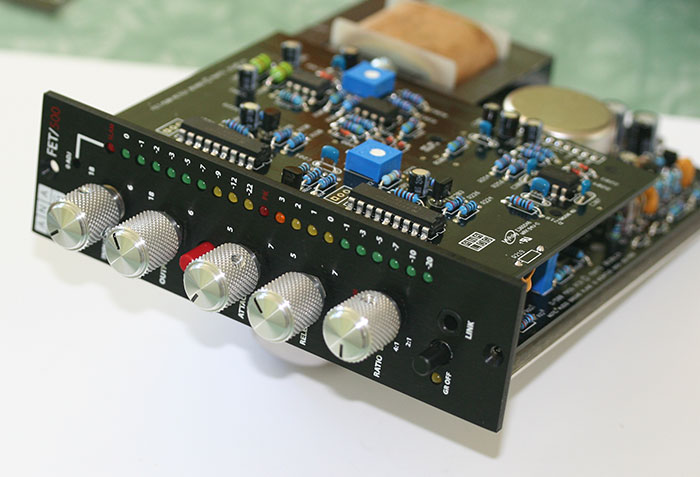
They are simply mounted flush to the PCB. Here are all of the front controls mounted with the Grayhill retaining sticker in place.
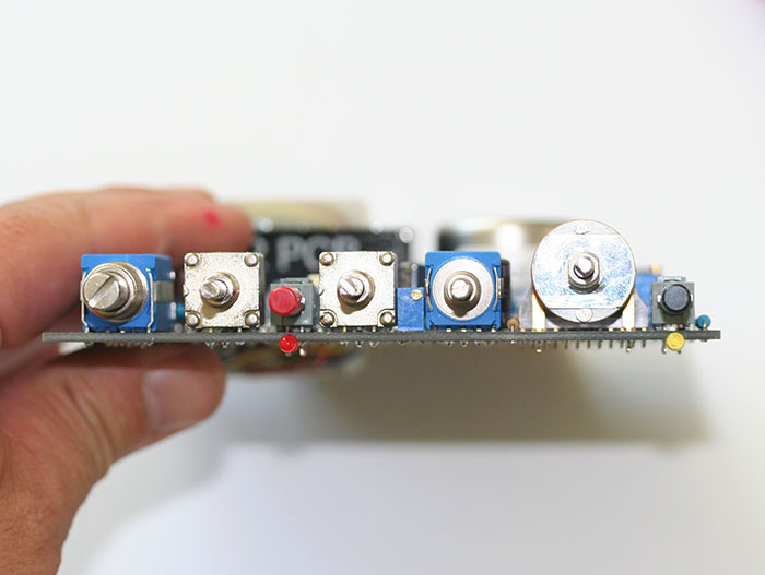
Note the QBias that sits between the Attack and Release pots.
Header
Install the 10 pin header on the top side of the PCB.
Press it firmly down so it sits flush to the PCB.
Transformer
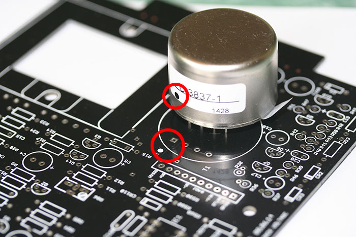
The CM-3837-1 input transformer is our version of the famed UTC O12. We believe it's the most accurate version.
Install the transformer by aligning pin 1 with pin 1 on the PCB. Pin one on the transformer and PCB are identified with a dot. It's a good idea to leave a small air gap under the transformer to avoid shorting the top pads with the transformer can.
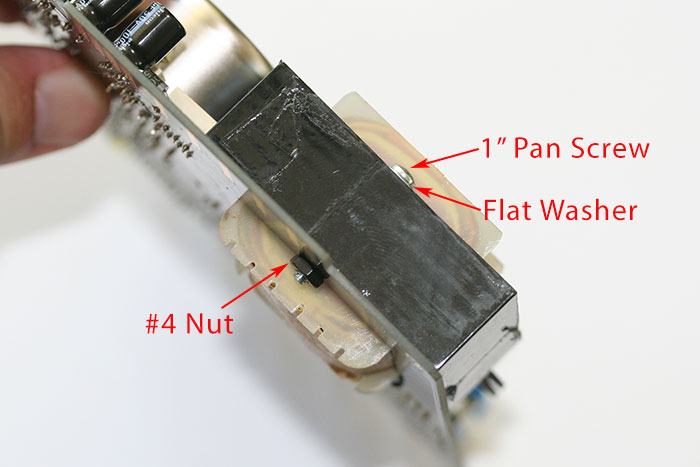
To install the output transformer, grab the two 1" #4-40 screws, #4 flat washers, and #4 nuts from the hardware kit. Place a flat washer on a screw and insert it into the side of the transformer with no wire. Mount the transformer so the wires are on the bottom of the PCB and secure it in place with the nut at the bottom.
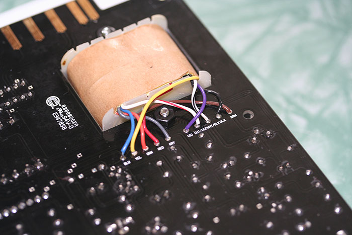
Note the wires are on the bottom side of the PCB. Now trim the wires to an appropriate length and solder them to the pads following the color codes.
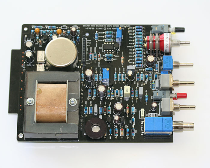
Bottom of the PCB. Note the wires are trimmed shorter for cleanliness and to avoid unwanted circuit noise.
Your main PCB is now stuffed!
VERY VERY IMPORTANT: Although we call the smaller PCB the "Meter PCB", it does more than just control the metering. It also supplies the negative rail voltage. Your FET/500 WILL NOT work without the meter PCB stuffed and connected.
Meter PCB
Assemble the meter PCB using the same steps used to stuff the main PCB.
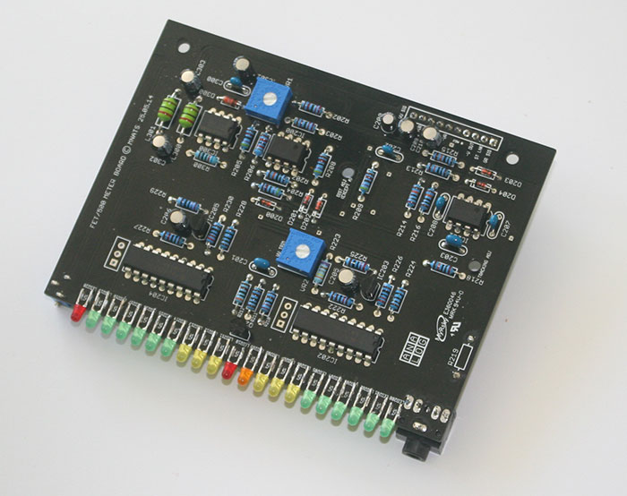
The meter PCB has a couple of components you have not yet encountered. One is the axial inductors, L200 and L201. These are the same value and are non-polarized. Treat them just as you would resistors. The other is the re-settable fuse located in R219. It is also non-polarized. You'll need to pinch and wiggle it a little to get it in. The header is a tight fit but you must get it in flush to the PCB. There are four BOTTOM MOUNTED parts.
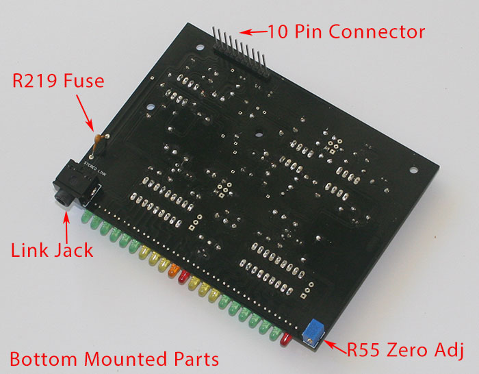
Note the fuse, connector, link jack, and R55 are all mounted on the bottom of the PCB. Mount the LEDs the same as you did on the main PCB by surface mounting or through-hole depending on your PCB revision as noted in the main PCB LED mounting section. Again, don't solder them in place until they are aligned with the faceplate. We recommend only mounting 3 or 4 at a time.
Meter Modes
The meters operate in "DOT" mode by default. This means only the top active LED is lit. The opposite is "BAR" mode which is more traditional and shows all active LEDs. We chose DOT mode as the default for both the GR and VU meter to keep the current consumption of the module inside of an acceptable value (150mA). If you have a rack with more available amperage per slot, or you have some modules that use very little amperage, you can choose to operate one or both meters in BAR mode be linking the two circular pads. With no link in place, or the square and circle closest to it linked, the meter will operate in DOT mode. There is a DOT/BAR jumper for each meter at the end of each of the LM3916 ICs.
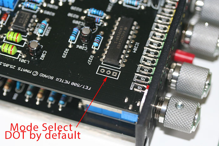
Meter shown in dot mode.
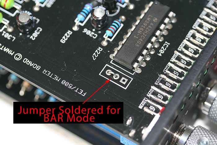
Solder jumper here for BAR mode.
Final Assembly
Start by mounting the two 1/4" standoffs on the L-bracket using the two #4 undercut screws.
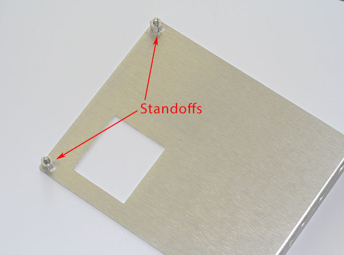
Screwed in through the bottom with the #4 undercut screws. Now mount the main PCB and Meter PCB and secure it into place with two #4 nuts.

Secure with nuts, meter board unmounted. You can mount it now. To mount the meter PCB simply align the 10 pin connector to the header and press it into place. It will wobble a little but the faceplate will eventually secure it in place. We will continue with the final assembly, but now is the point at which you would want to calibrate while the q-bias is accessible through the bracket. It's time to plug it in!
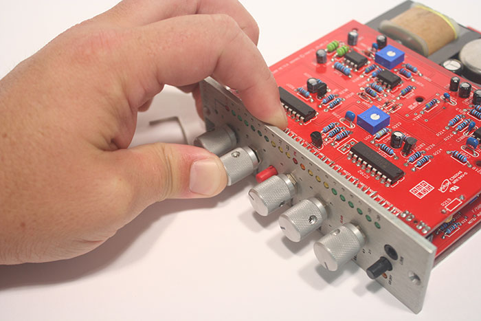
To calibrate now (which you should) scroll to the bottom. Once you are done calibrating slide the front panel onto the unit and secure the pots and Grayhill with their supplied nut. There may not be enough depth to use the toothed washers, that is fine.
Now you can attach the knobs and secure them with a 1/16 hex key. You'll have to float the T-pad and Grayhill pots a little off the front panel if you want all the knobs to be even.
Knob/Potentiometer Rotational Torque Adjustment
You may notice that your controls have different rotational torque. Some may have a lot of physical resistance as you turn or feel "tight", while others have a "looser" feel. It's a misconception in pro-audio that tight turning pots are better quality pots. The rotation torque has nothing to do with quality. You'll note any grey pots in your kit will have a looser torque than the blue pots.
Here is a little trick used by many high-end manufacturers. Start by locating the bag in your kit containing the rubber o-rings. You will have 3 o-rings for every grey pot you have. You might have anywhere from 0-3 grey pots depending on your purchase date. Slide three o-rings over each grey pot shaft. In this case, we're using the output pot as an example.
Push them tightly against the shaft bushing.
Now place the knob on the shaft and push downward on the knob and you secure it in place with the set screw. This will squeeze the o-rings against the bushing adding rotational torque.
You'll have to experiment. Too much pressure may make the torque feel springy and not enough won't help. We've found adding three o-rings with the right pressure to the input, output, and attack can make them feel almost identical to the release.
Calibration
If you don't have a 500 series edge card extender, you'll calibrate your FET/500 unit inside your rack. The trimmers are accessible, but you will need to keep a few slots to the right open. Perform the calibration with the faceplate removed and the unit warmed up for 20 min. You may want to consider re-calibrating after a week of use/burn-in. At no point should your unit be in full bypass (RED Switch) while calibrating. I'll explain the calibration in two methods. Method one assumes you have the proper tools and understand basic calibration procedures. Method two is for newbies with only a 500 series rack, DMM, and DAW. Method two will be in video format.
Calibration Method 1: I'm fancy, I know what I'm doing
Step 1 - Qbias Adjustment. This is the most important adjustment since it actually affects how your unit compresses. In this step, we're going to set the FET slightly into conduction.
- Set Input and Output to midway
- Set Attack and Release fully clockwise
- Ratio at 20:1
- Put the unit in GR Off mode
- Apply a 0dBu (0.775 VAC) 1KHz signal to the FET/500 input
- Observe the output level and turn the Qbias trimmer counter-clockwise until the output level reaches a maximum value and no longer increases. The FET is now in "pinch off"
- Adjust the Output control so the FET/500 output reads +11 dBu (2.75 VAC)
- Rotate the Qbias clockwise until your output drops by 1 decibel to +10dBu (2.45 VAC), it will happen quickly
Step 2 - VU Meter Calibration:
- Set Input and Output to midway
- Set Attack and Release fully clockwise
- Ratio at 20:1
- Put the unit in GR Off mode
- Apply a 0dBu (0.775 VAC) 1KHz signal to the FET/500 input
- Adjust the Output control so the FET/500 output level reads +16 dBu (4.88 VAC)
- Adjust the VR1 "Gain Trim" on the meter board so the RED "Peak" LED starts to illuminate.
- Adjust the Output control so the FET/500 output level reads -6 dBu (0.388 VAC)
- Adjust the VR2 "VU Trim" until the -10 LED LED starts to illuminate.
Remember that this meter reads 0dBu = +4dBu like the original units. So the -10 dBu LED is equal to -6dBu. Step 3 - Gain Reduction Tracking
- Set Input and Output to midway
- Set Attack and Release fully clockwise
- Ratio at 20:1
- Deselect GR Off so your unit is now in GR mode
- Apply a 0dBu (0.775 VAC) 1KHz signal to the FET/500 input
- Adjust the Output control so the FET/500 output reads +0 dBu (0.775 VAC)
- Put the unit in GR Off mode
- Adjust the Input control so the output reads +9 dBu (2.18 VAC)
- Repeat the last 4 bullet points until you see an output of +9dBu in GR OFF mode and an output of 0 dBu in GR ON mode
- With the unit in GR OFF (9 dBu output) adjust the "0 Adj" trimmer located on the front panel near the input knob so the 0 illuminates
- With the unit in GR ON (0 dBu output) adjust the "Tracking Adj" located on the main PCB and accessible through the meter PCB so the -9 LED illuminates
- Repeat the last 2 bullet points until you see GR meter dropping between 0 and -9 just like your output level.
Step 4 - Signal Preamp Linearity (Rev D and F Only)
- Set Input fully CW and Output to "18"
- Set Attack and Release fully clockwise
- Ratio at 20:1
- Put the unit in GR Off mode
- Apply a -30dBu (0.0245 VAC) 500Hz signal to the FET/500 input
- Adjust the "Dist Adj" located on the main PCB and accessible through the meter PCB for lowest THD
Method 2: Calibration inside your rack with a DAW and DMM
We did not include step 4 (Signal Preamp Linearity) because it can not be done with basic tools. It is not an overly important adjustment. It adjusts a 100Ω trimmer for the lowest THD. Generally, at best this is 0.05% and at worst it's 0.1%. Both of which are fine. There are a number of free programs you can download onto your computer that can use your A/D interface to send a signal and measure THD. Simply download and install one of those and follow the step 4 instructions above.
If you find a program that is free and works well, send us an email and we'll post it here.
You're done!
Note about the GR Meter
The GR reduction meter has an operates like the Analog VU in that the Red SLAM LED is just the + right side of the meter. If you twist the zero adjust you'll see you can go into the red as it's not separate, but an extension of the GR meter. Putting the unit in SLAM pegs the analog meter far-right which means in the LED version it pegs it to the top. In SLAM mode GR metering is jittery and inaccurate, just like the analog meter.
Finding your input a little hot? Check out our Input Mod Page for some information and a solution.
500 Series Racks with Pin 6 "Link" Connected By Default
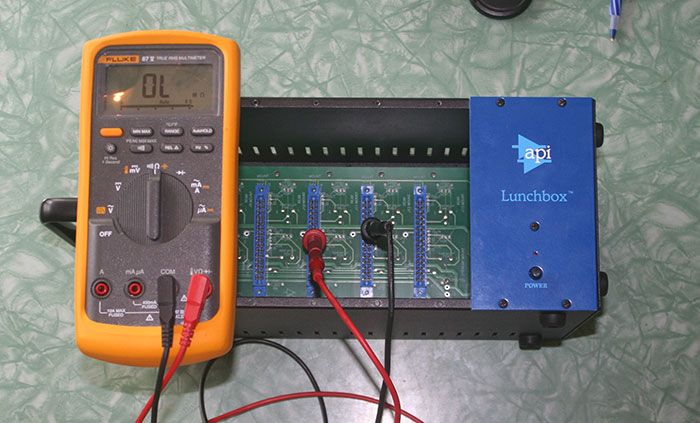
If you have a V1 PCB and a rack that has all connector pin 6 connected by default, having two FET/500's in your rack will cause them to operate in link mode by default. 99% of racks do not have pin 6 connected by default. The only rack we currently are aware of that does this, is the newer API lunchbox racks with the DB25 connectors on the rear. If you own any other lunchbox, it's safe to assume yours does not. If you want to be sure, simply set your DMM to read resistance (Ω) and measure between pin 6 of any two modules in your rack (count 6 down). It should be infinity/overload. Your unit does not need to be powered on. In fact, for safety reasons please unplug it.
Count 6 pins from the top of the edge connector. These pins are not linked. Note: This is an older non-DB25 API rack and these units are NOT connected by default. This means no trace cutting is needed. If you do have a new API lunchbox with DB25 connectors, you'll need to cut the trace on the FET/500 PCB that connects to pin 6. This does not affect your unit in any way and your front panel linking will still work. This pin 6 trace is a redundant trace that is not needed. Simply take and x-acto style knife and score a V int your PCB and break the trace. The trace in on the top/component side of the PCB. It's the 6th pin from the top.
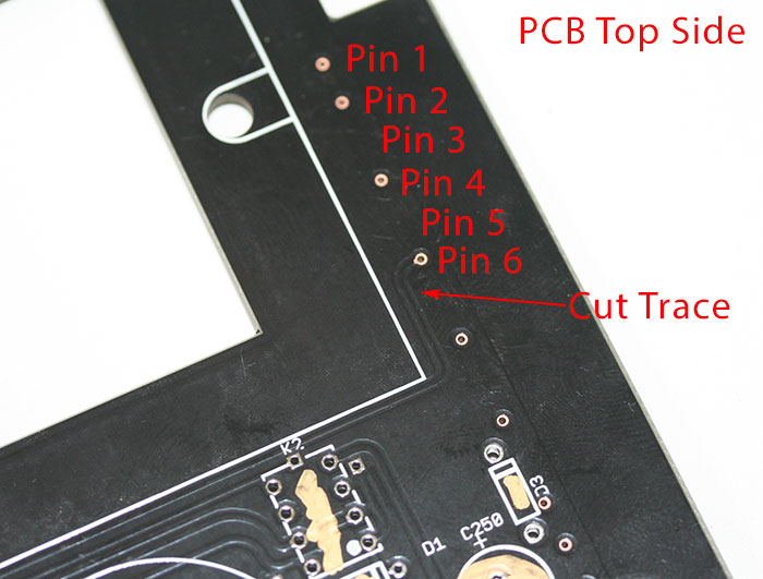
Note that pin 3 and pin 5 are not used in the FET 500 so those spaces are blank.
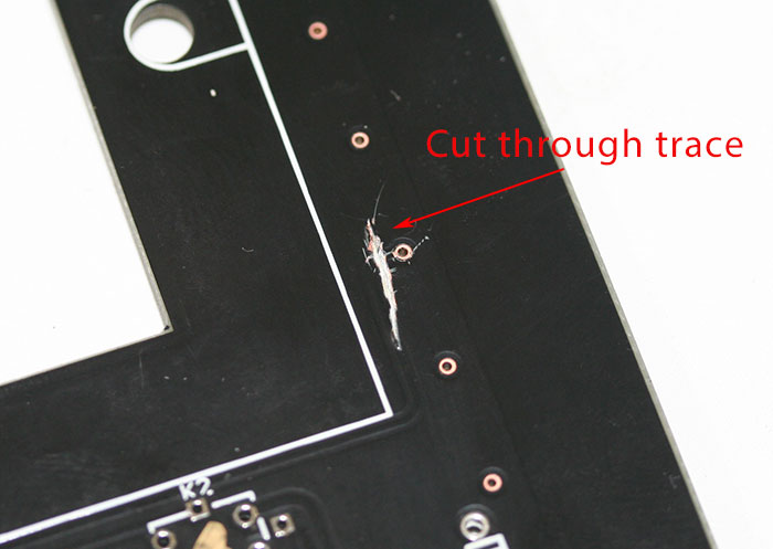
This is on the top/component side of the PCB. Don't be shy about cutting it. The newer DB25 API Lunchbox actually has 0Ω resistors connecting the pin 6s. If you look inside you can see them labeled "Comp Link". If you don't want to cut a trace on your PCB, you can simply cut out or desolder this resistor. If you have your FET/500s in space 1 and 2, cut out the resistor that sits in the "Comp Link 1-2" spot.
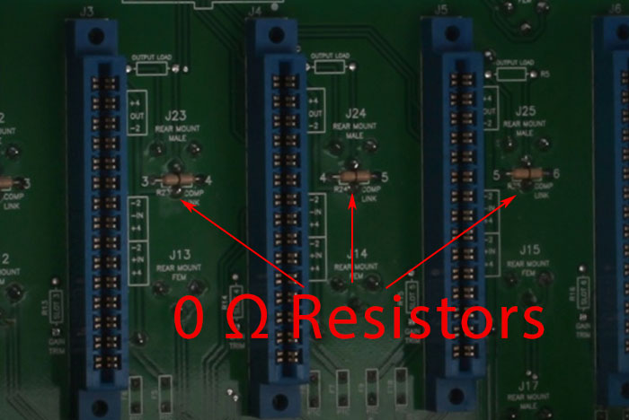
0Ω resistors present in the API Lunchbox with DB25 connectors.