Getting Started
Choosing to build your own piece of gear can be a rewarding and great learning experience. However, it can also be frustrating and time consuming if you choose to rush through the build paying little attention to detail. As much as you want that cool new piece of gear up and running NOW, take your time and make sure to take breaks. Move through each step carefully, take pride in your build. A sloppy build, even if it's working, won’t give you the same sense of satisfaction as that of a good, clean, and neat build. Patience is key to the success of your build.
We STRONGLY suggest you start by reading this entire build guide before beginning your build. It'll give you a better idea of what is involved and how it all gets put together.
Tools
You’ll need a few basic tools to complete this build. Though this list may not be exhaustive, it’ll give you an idea of what you should have on hand.
- Soldering Iron It goes without saying that you need a soldering iron, so get a decent one. At the very least you should have a 25-watt pencil-style soldering iron. Weller sells the WP-25 for about $40 USD and it’s a solid entry level soldering iron. Radio Shack sells a 40-watt model for about $10 USD. I’ve not used that model, but I bet it’s better than a lighter. If you’re going to build a few units and do some repairs, consider getting an adjustable temperature solder station. The Hakko FX888D is a tried and tested unit that sells for about $120 USD. It’s a fabulous tool.
- Soldering Tip Most decent irons will allow you to insert different tip styles. For most PCB work, including this build, you’ll want a small chisel tip. I use the Hakko FX888D iron with a T18 chisel tip. This is a 1.6mm width chisel tip appropriate for the average pad width in this build.
- Solder Solder is kind of like guitar strings in that you really need to feel which one is right for you. I went through a few types before I found one I liked. There are a few different considerations such as lead or lead-free, no-clean type, and the diameter. I use Kester #245 no clean solder. It's a 0.031” diameter 63/37 alloy (Part #24-6337-8800). It's advertised as a no-clean solder, however, the bottom side of your PCB should still be cleaned with isopropyl alcohol after your PCB is stuffed. We've found any amount of flux residue on high impedance portions of this circuit will alter the attack and release.
- Digital Multi-Meter (DMM) A good DMM is as important as a soldering iron. An auto-ranging DMM will make sorting resistors a breeze and help avoid time-consuming errors. Testing and troubleshooting will make having a good DMM a must. An inexpensive model is better than nothing, but a good model will be a trusted tool on your bench and in your studio for years. It’s important to note that cheap meters generally do not measure AC (audio) level accurately above a few hundred Hertz at best. In audio we like to deal with 1KHz test signals, so get a nice meter. Fluke is the standard for DMMs. A Fluke 177 is another tried and tested workhorse. It’s not cheap, but it’s not that expensive for something you will use and depend on every day.
- Panavise Do you need a Panavise? No. Will it make your PCB stuffing much easier and make you look cool? Yes! These are not that expensive. Consider getting one.
- Pliers, Cutters, and Strippers A pair of fine needle nose pliers will come in handy for some of the final assembly work. I bet you already have a pair of these! Small diagonal cutters are a must. You’ll need these for trimming the component leads. Having a decent pair of wire strippers in the 16-26 AWG range is something you should have.
- Hex Key Set Also known as a Hex Wrench, Allen Wrench, and Allen Key. Whatever you call it, you need one to install the knobs. Consider getting an imperial set with a nice storage case.
- Nut Drivers These are not as fun as they sound. These are used to tighten various nuts in assembly, including the faceplate components. Due to the length of the potentiometer and t-pad shafts, you’ll need a nut driver with a fairly deep channel. I used to use pliers to tighten these. I’d mar the nuts, scratch the panel and drop a few F-bombs. Do yourself a favor and get a Nut Driver set. I picked up a 7 piece set at a hardware mega-store for about $15.
Soldering Guide
Soldering WELL is one of those things that seems easy until you try it. Once you try, it starts to seem kind of difficult. Then finally you figure it out and it seems easy again.
Rather than trying to explain it to you, I went online, to find the best video tutorial I could. I settled on Dave Jones’ tutorial on the EEVBlog. Dave’s a wacky cat, but so are most guys who inhale lead all day. The tutorial is presented in three parts: tools; soldering through-hole components, and soldering surface mount components. For our purposes, I recommend you watch part 1 and 2. The videos are lengthy at about 25 minutes each, but they are well worth watching. Even I learned a few things.
The videos can be seen by visiting:
hairballaudio.com/eevblog-solder-tutorials
FET/RACK Documentation
Below are helpful tools for completing the build. The interactive build map helps you locate and checkoff components as you populate the PCBs. The searchable PDF BOM can be printed or opened and searched via your browser's search function. It also includes the schematic.
Revision A Interactive Build Map (PCB V1.15 and Earlier)
Revision A Interactive Build Map (PCB V2.0 and Later)
Revision A Searchable PDF BOM, Schematic, Board Layout
Revision D Interactive Build Map (PCB V1.15 and Earlier)
Revision D Interactive Build Map (PCB V2.0 and Later)
Revision D Searchable PDF BOM, Schematic, Board Layout
Revision F Interactive Build Map (PCB V1.15 and Earlier)
Revision F Interactive Build Map (PCB V2.0 and Later)
Revision F Searchable PDF BOM, Schematic, Board Layout
All Revisions: PCBs V2.0 and higher have R-OPT on the mainboard by the input t-pad. It is NOT supplied with the kit. It's an optional mod to tame the input if you feel you need it. You can use any 100Ω resistor 1/8W or higher that will fit. Details can be found on the input mod page. If you're not using the mod, leave that space empty. The revision A has another R-OPT on the ratio PCB. It is a 10MΩ resistor and is supplied with your kit. You should install it. It is a resistor that will prevent a popping sound when switching ratios. It was added to the Rev C and beyond. If you want to be 100% authentic to the Rev A, you can leave it empty.
FET/RACK Introduction
Now on to the build! Actually, not just yet.
Before you begin your build, confirm that you have the correct PCB for your intended build. The FET/RACK is currently available in three revisions. The revision A "Bluestripe", based on the more stable revision A/B, and the revision D commonly referred to as the "Blackface". The revision F was also a "Blackface" unit, however, we've added a red stripe to differentiate it from the D. The PCBs that arrive will be color-coded.
Revision A: Blue PCBs
Revision D: Black PCBs
Revision F: Red PCBs
Please note this build guide contains mostly images showing the revision A blue PCBs however, the process for building the revision D and revision F is the same unless noted. Only the component values change and the calibration is slightly different. Any differences between building the revisions will be clearly noted in this build guide.
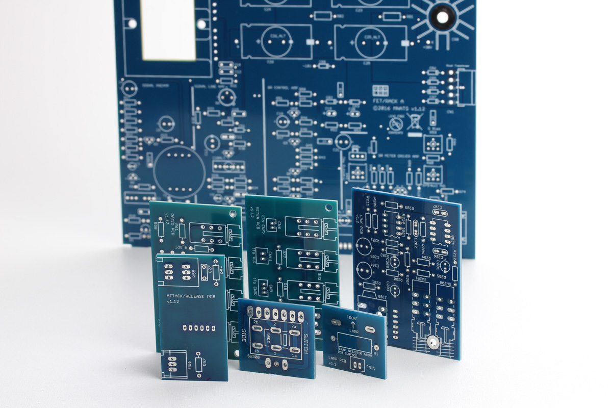
Above is a complete set of PCB's, revision A, including the optional active stereo link board.
Complete set includes:
Back Row: Main PCB
Middle Row L-R: Ratio, Meter, Active Stereo Link (sold as an add-on)
Front Row L-R: Attack and Release, Voltage Select, VU Lamp
Lastly, it's a good idea to do a full inventory of your kit. We're human and we mess up sometimes, if you're missing a capacitor or resistor visit http://hairballaudio.com/missing and we can get you a replacement while you work on the rest of your build.
Building and Testing the Power Supply
Now we can start! The first step in the build is to successfully and safely build the power supply. Building and testing the power supply before completing the rest of the board will help avoid complex and hard to diagnose issues later in your build. Building the supply will require that you install some common components like resistors, capacitors, and diodes. Identifying and installing these parts is covered in detail in the populating the PCBs section. If you have any doubt, look ahead to those sections. Again, it's best to read the complete build guide before you start.
Unless noted, the parts needed to complete the power supply are in the two boxes of labeled Power Supply 1 and 2. Start with the voltage select PCB.
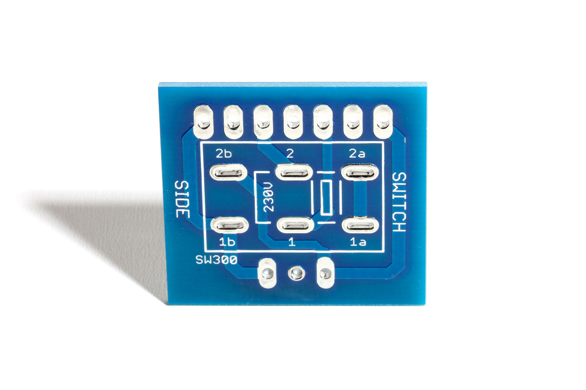
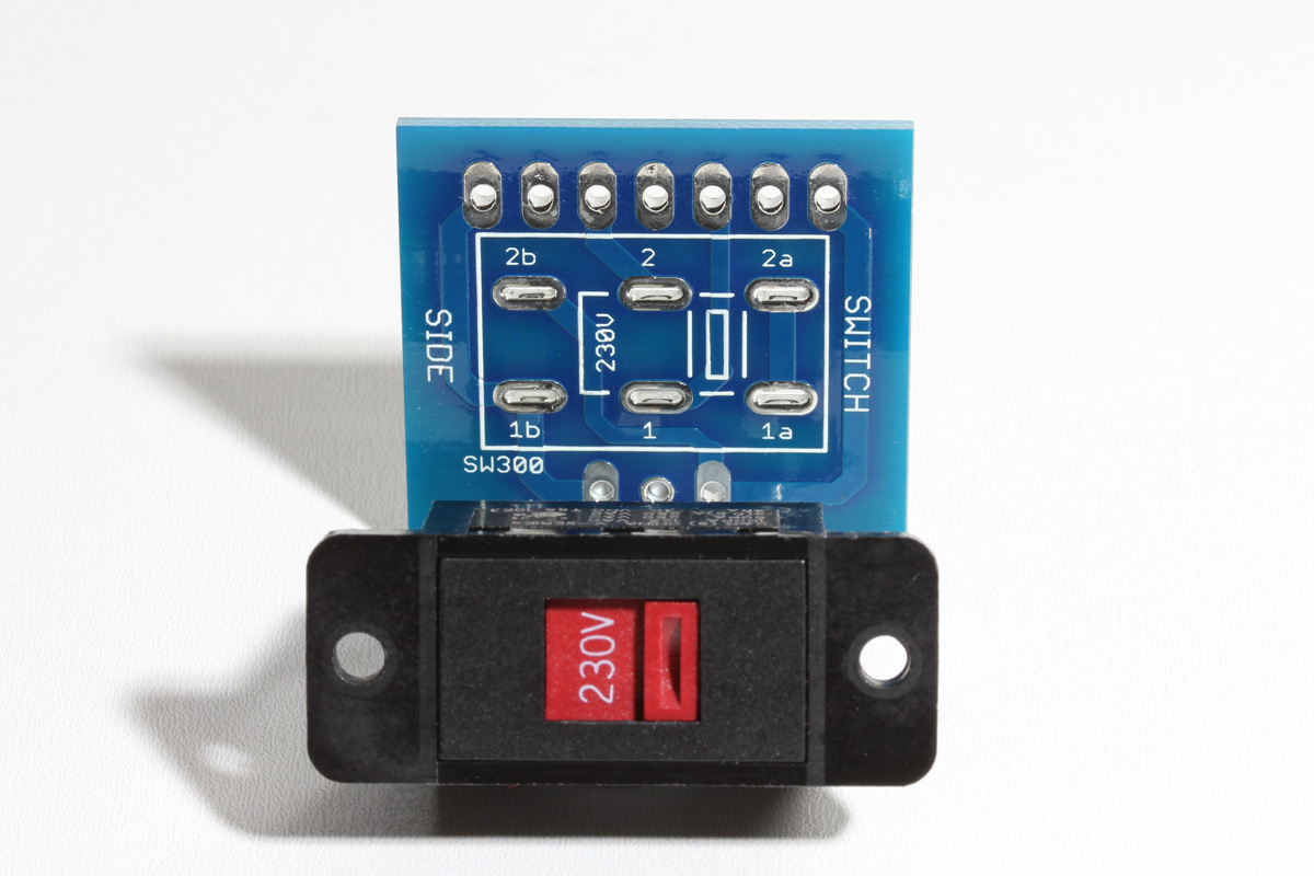
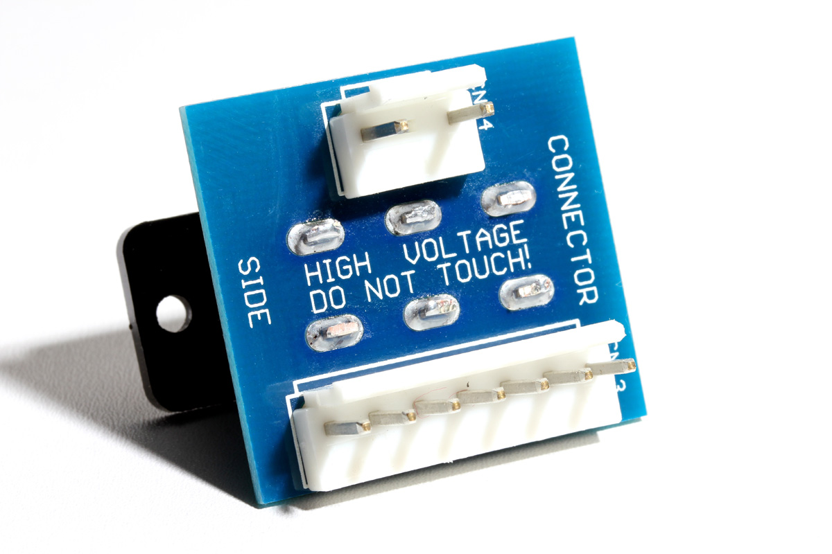
Notice the silkscreen on the switch side. Pay attention to the orientation of the 230V label as well as the 1b-1-1a and 2b-2-2a labels on the solder pads. Now grab your voltage select switch.
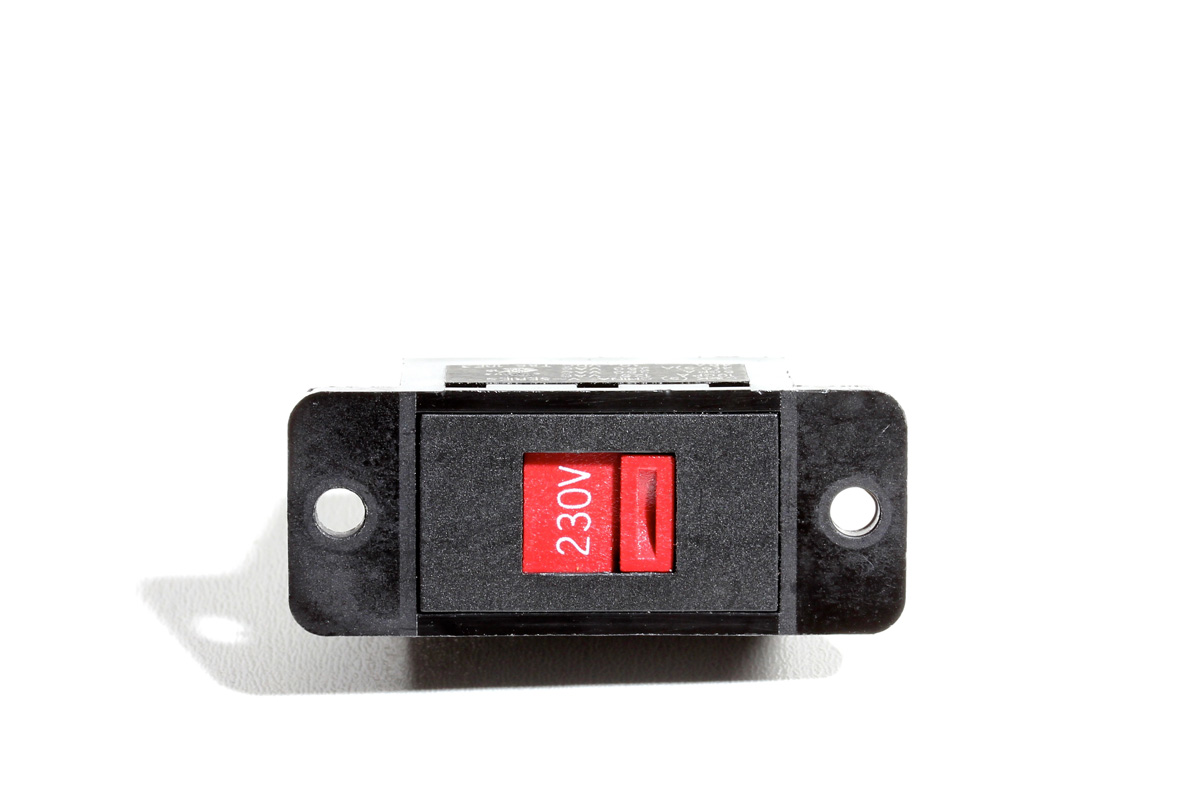
Switch it to the 230V position as shown regardless of your local mains voltage. Having it in the 230V position will help you to confirm you've soldered it to the PCB in the correct orientation.
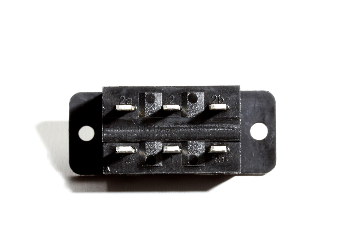
Flip the switch over and you'll see that the terminals are labeled with 1a-1-1b and 2a-2-2b just like the voltage select PCB! Perfect, now line them up on the switch side of the PCB so those terminals enter the same pads on the PCB.
Once the terminals are oriented to enter the correct solder pads, you'll also notice that the 230V label and switch match the orientation of the silkscreen.
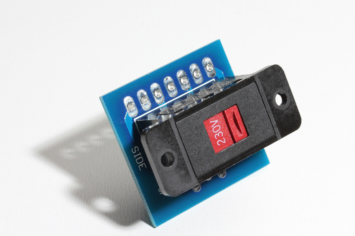
Here it is inserted. Press it so it sits tightly and level on the PCB.
Before soldering, trim the terminals to prevent interference with the CN13 and CN14 connectors. It will also make them easier to solder, the less surface area you have to heat, the easier it is to heat and solder. Don't trim the flush to the PCB! Just trim them about halfway.
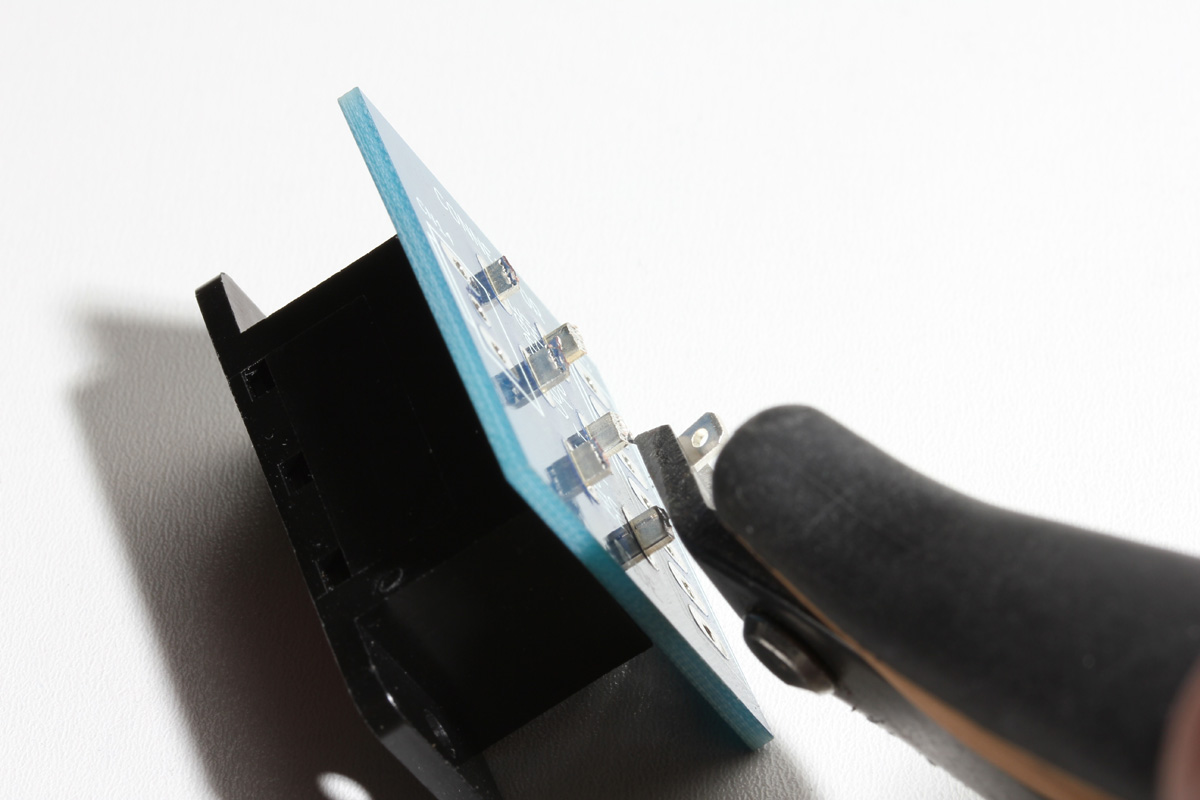
Now carefully solder the terminals. Again, make sure the switch is placed tight and square to the PCB. Solder one terminal then confirm the switch is sitting properly before soldering the remaining terminals.

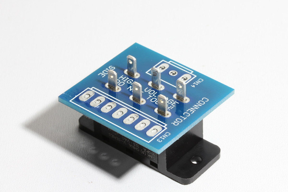
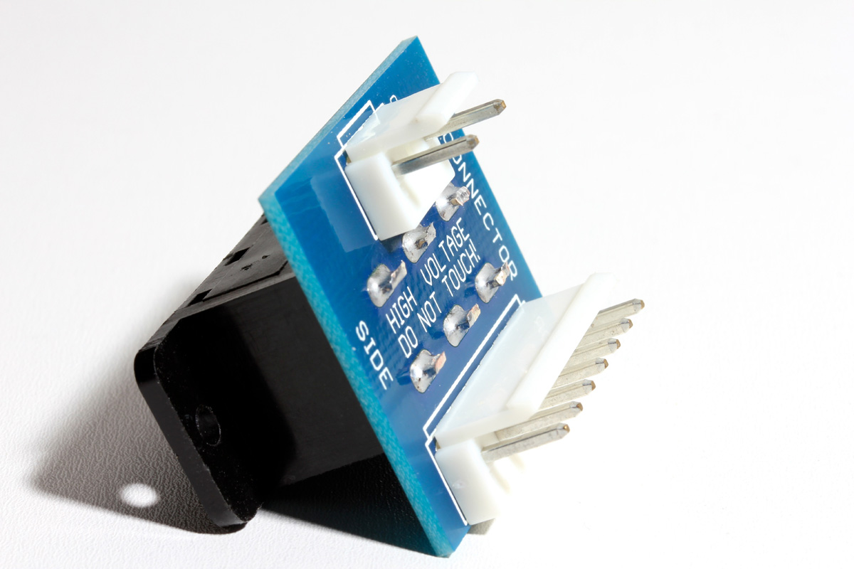
Now you should have a nicely soldered and trimmed voltage selector switch. Locate the two connectors for CN13 and CN14 and mount them on the connector side of the PCB paying close attention to the silkscreen orientation. Note that your CN14 will have 3 pins, not 2 pins as shown in the image below.
Now you can solder them on the reverse side. Again, solder one pin and confirm the connector is fitted tightly and square before soldering all of the pins. When you've completed you should have a completed voltage select assembly.
If you live in a 115V mains region, you can go ahead and flip the switch to the 115V setting now.
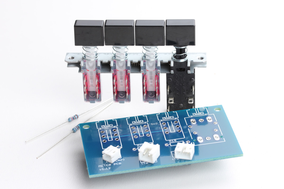
Next, locate the meter PCB, meter switch, and components. The meter PCB will be the other PCBs and the meter switch will be in the loose parts. The two resistors will be located with the main components. The three connectors should be in your power supply box.
Locate and insert the meter resistors.
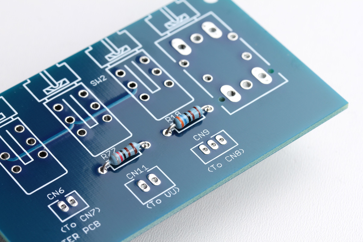
Now you can solder the reverse side. To keep the resistors flush on the PCB, bend the resistor legs out at a 45-degree angle, this will hold them tight to the PCB.
From here there are two schools of thought. You can trim the leads just above the PCB then solder. This will result in the best joint as the inner core of the lead can receive the protective coat of tinning from the solder. But it leaves open the possibility that you may miss a joint as a trimmed lead looks a lot like a soldered one.
To reduce the possibility of missing a joint you could solder the lead, then trim it. But a thick lead will act as a heat sink making soldering more difficult. The resulting joint might be somewhat less reliable in the long run but will reduce the chance of mistakes. Make a choice based on your work habits and personal preference.
Notice the solder joints here. There is a small amount of clean shiny solder, not a big dirty blob.
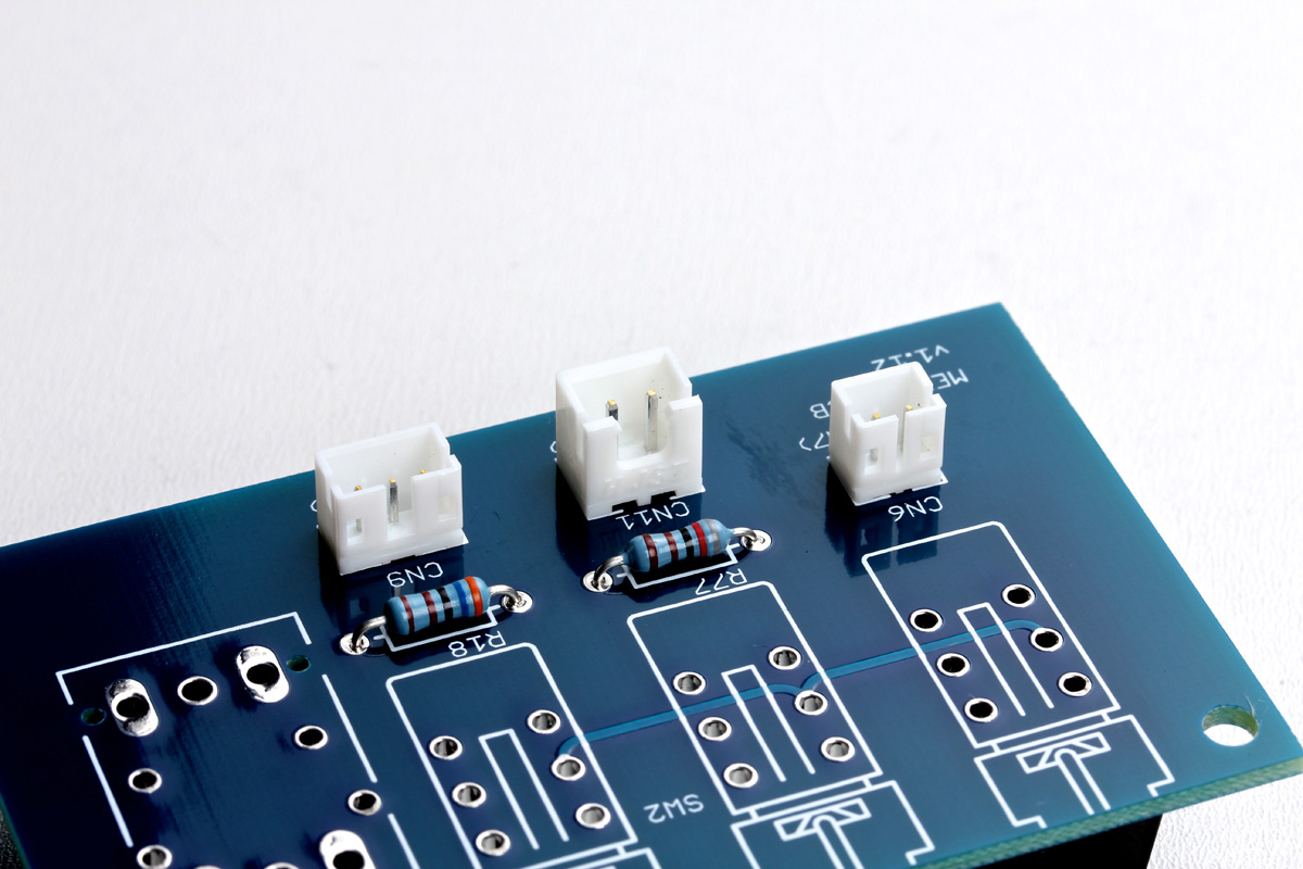
Now locate the connectors CN6, CN9, and CN11 and place them on the top side. The silkscreen will help you to orient them.
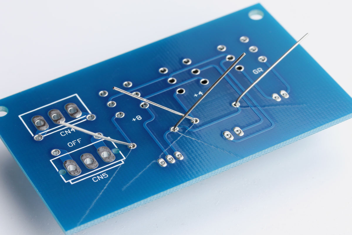
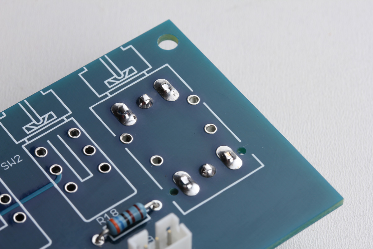
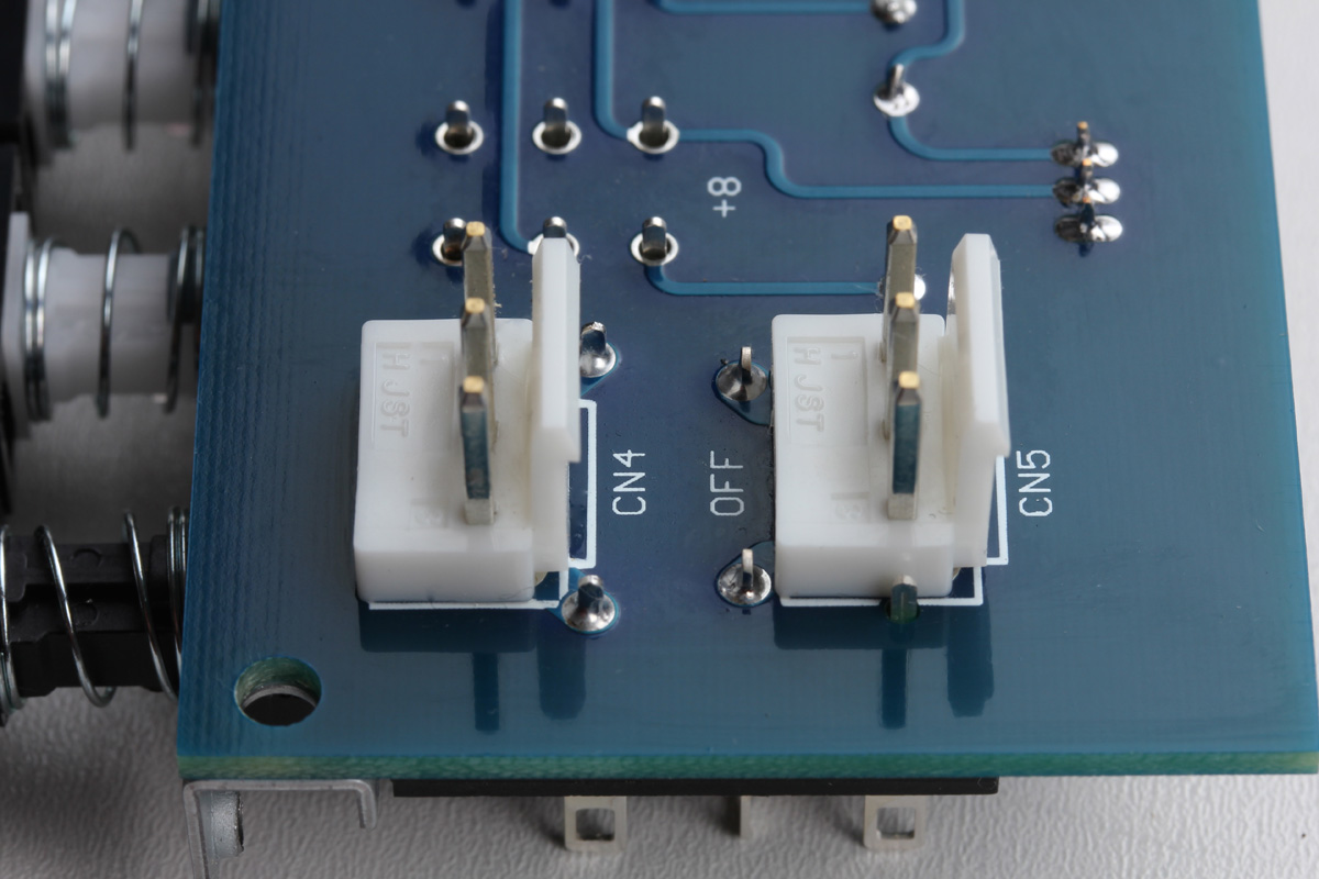
Solder the bottom side and once again confirm they sit tight and square. Now locate CN4 and CN5 and insert them on the bottom side of the PCB following the guide on the silkscreen.
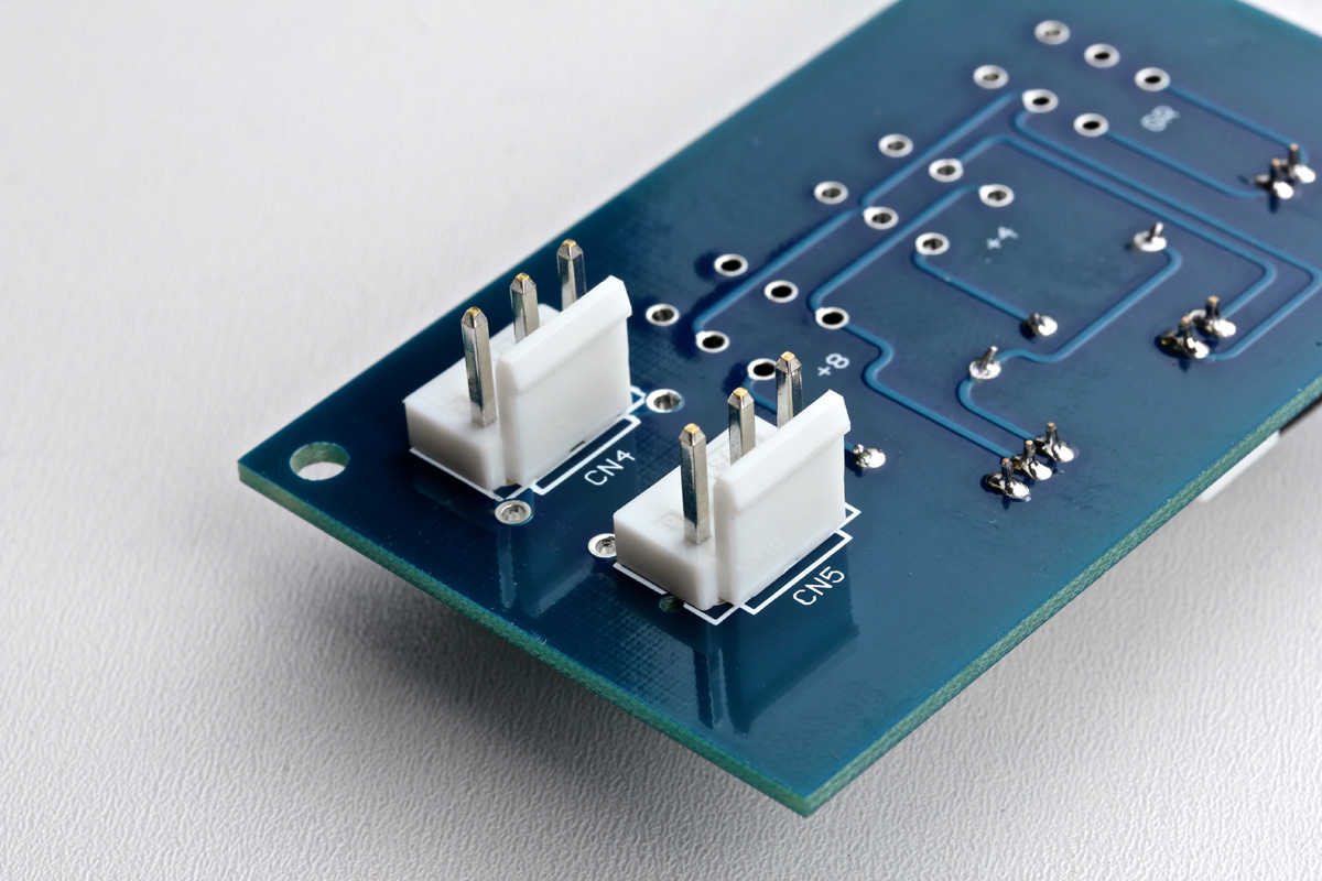
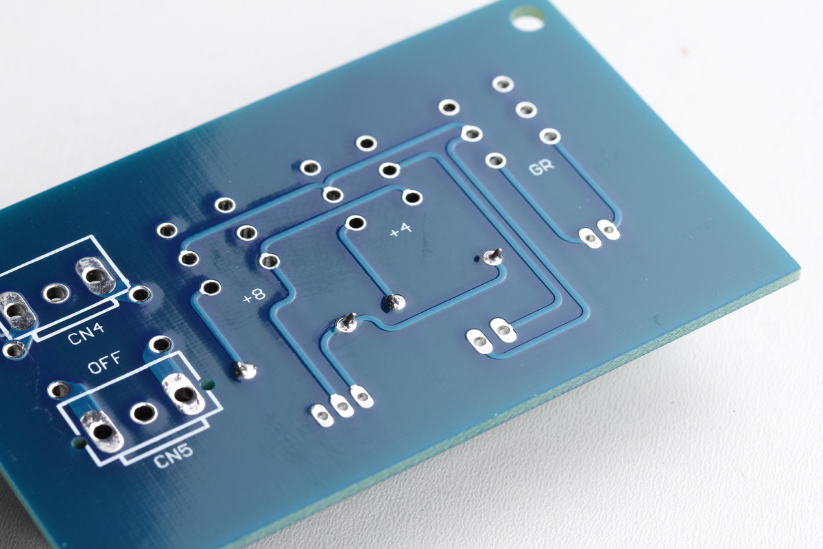
Solder them on the reverse side and, you guessed it, make sure they are tight and square on the PCB. Once soldered, be sure to trim the pins as shown. We'll need these pins trimmed as shown to safely install the meter switch.
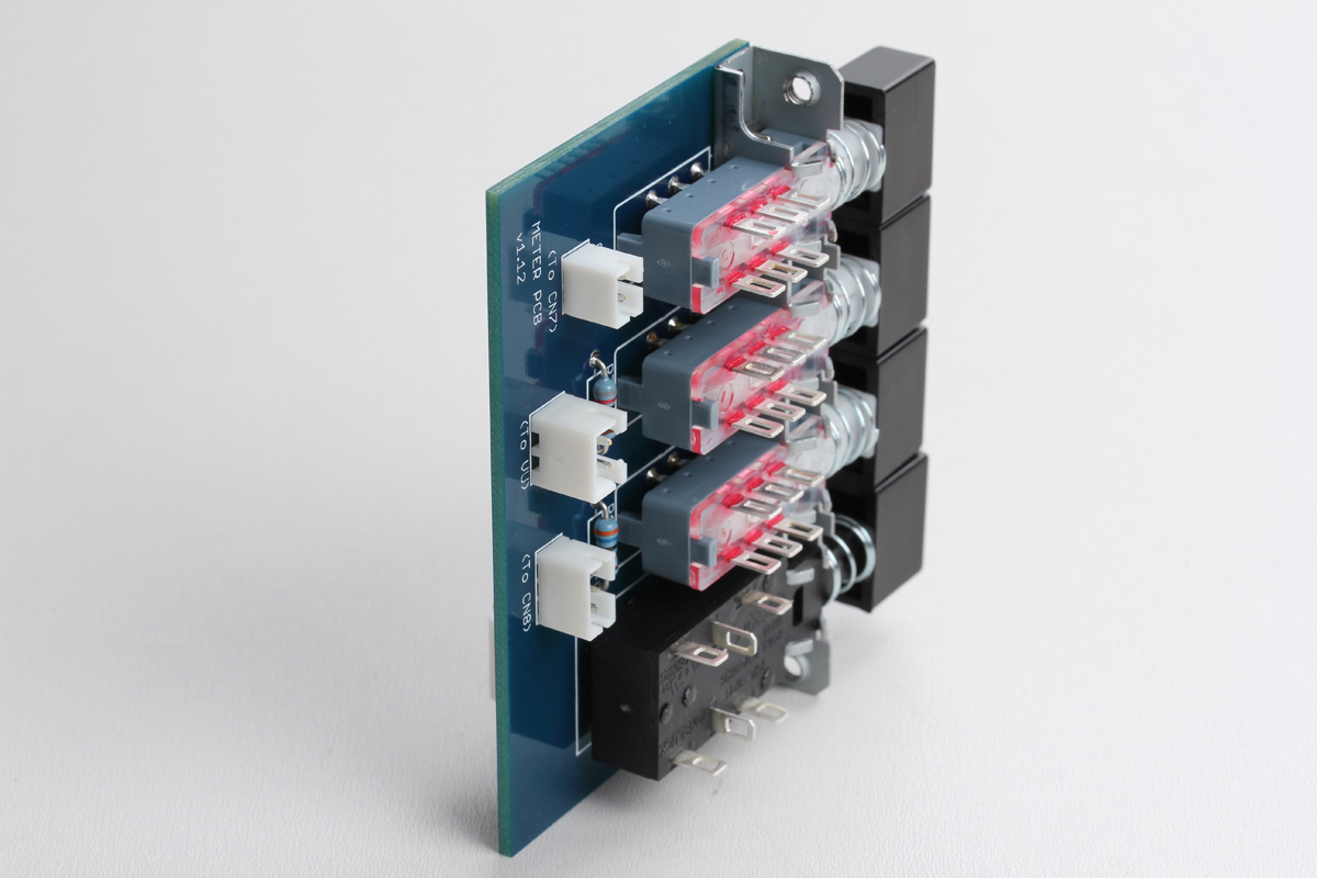
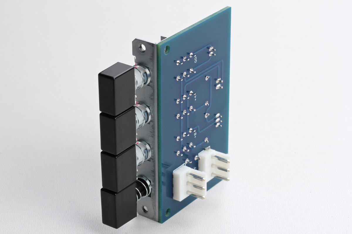
Locate the meter switch and install it on the top side of the PCB. It's CRITICAL that the switch is absolutely tight and square on the PCB, solder it slowly, confirming it's pressed tightly against the PCB after the first few solder connections are made. Note that on the OFF switch there are 6 solder terminals, however, only 4 of those terminal holes have silver pads on the PCB. You only need to apply solder to the 4 terminals with pads. Solder all 6 terminals on the +4, +8, and GR switches.
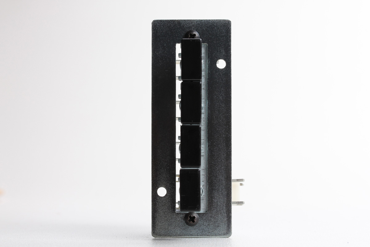
Below is a perfectly assembled meter switch assembly.
Let's talk about screws. There should be three bags in the JST/Screw Set box that contain only screws:
- 18pcs of #6 silver flat screws. These are larger in diameter and are for mounting the top and bottom enclosure panels.
- 4pcs of silver Plastite screws. These are a longer metric screw that looks similar to a #4 screw. These are for mounting the XLR connectors.
- 14pcs of #4 silver pan screws. These are short small pan screws that you'll use here and any other place we refer to "#4 short silver pan" screws.
Locate one of the switch brackets and mount it to the switch as shown using two #4 short silver pan screws. Note the orientation of the faceplate standoff holes in the upper right and lower left.
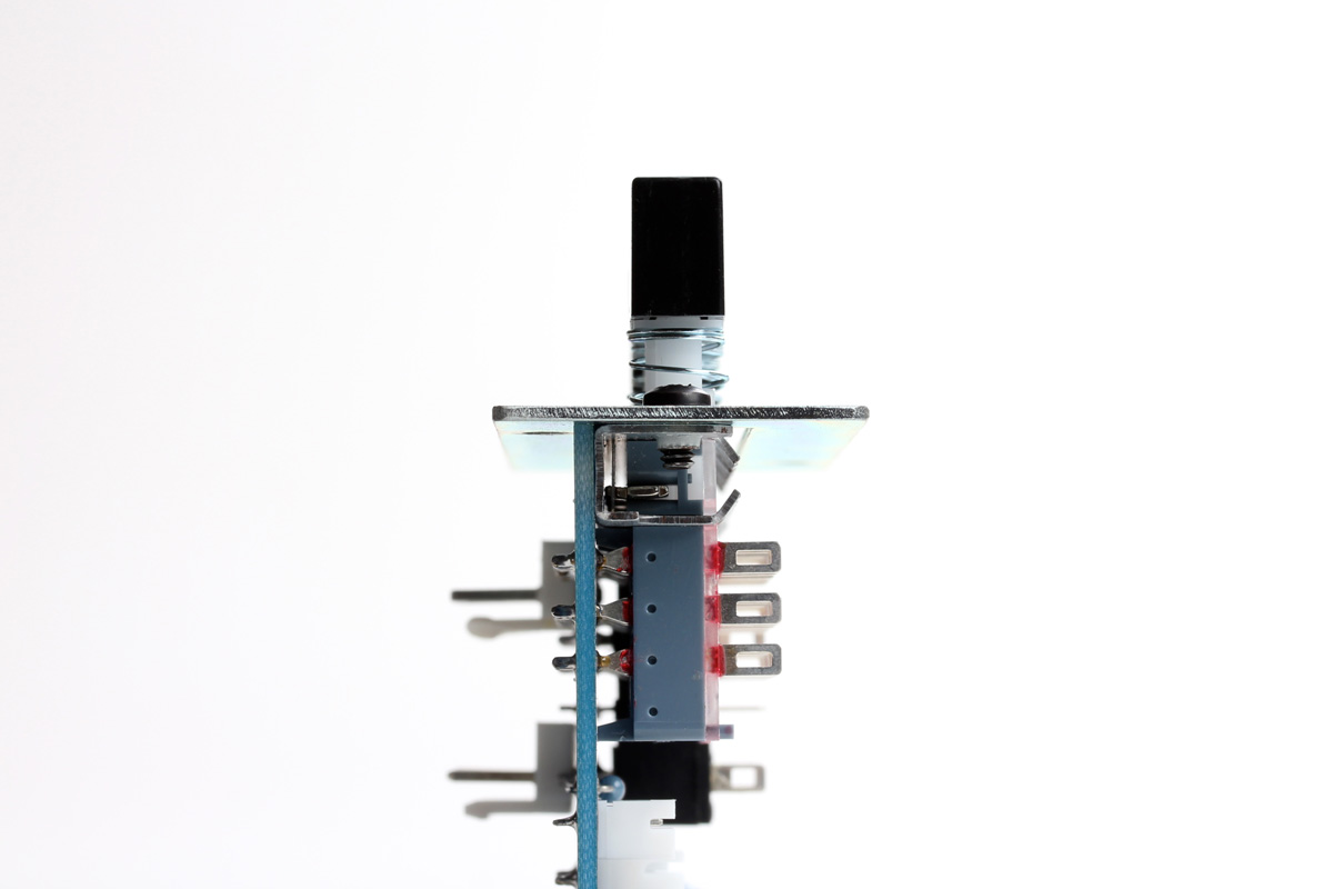
Examine the switch from the side like below. The switch and PCB should sit 90° from the bracket. The switch chassis may arrive from the factory not perfectly square, so if you see that the switch is a few degrees off from 90°, you can hold the bracket and switch tightly and bend it into place.
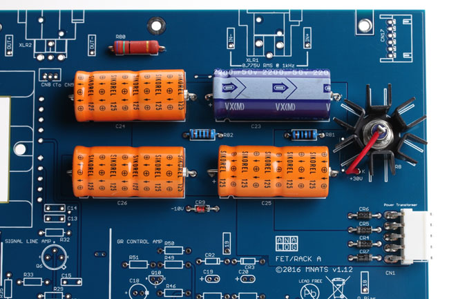
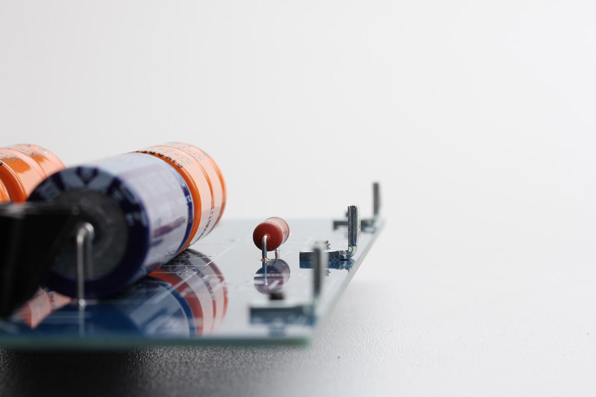
Finally, the last bit of soldering to complete the power supply circuit is located on the main PCB. Carefully solder all the power supply components located in the power supply boxes and confirm all are tight against the PCB with one exception, the resistor labeled R80. This resistor dissipates a lot of heat and should be mounted so it sits just off the PCB.
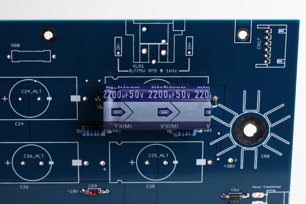
The large axial electrolytic capacitors three orange and one blue, are polarized. They must be oriented properly to avoid severe damage. Examine the orientation of C23 below, it's the blue capacitor here, but currently it's orange. It has a higher voltage rating (63V) than the other capacitors (40V) and must be placed in this location. On the revision F this location is C25. Note that the capacitor has a negative symbol with arrows pointing right indicating that lead is the negative lead. Also, note the capacitor has a ridge on the end with the positive terminal. Looking at the silkscreen you can see it also indicates the negative pad with a negative symbol and a ridge on the positive side. Insert the capacitors tight to the PCB. The board also has nested vertical footprints (radial) if you'd prefer to try a different capacitor.
CR8 is a 30V DC zener diode. It has an anode lead (-) and a cathode (+) lead. The anode is the side with the threaded bolt and it is NOT soldered to the PCB, but rather held in place with a nut and washer. Feed the threaded anode end through the heatsink base and then through the large circular pad on the PCB. Apply the supplied washer and nut on the bottom side and secure it in place. Do not overtighten, you may damage the PCB. A good rule of thumb is to tighten with a nut driver just beyond what you think you could do by hand. To connect the cathode or positive end, use the supplied pre-cut red solid core wire. Solder one end to the slotted tab and the other end to the pad labeled "K" which indicates cathode. If you're puzzled by the K designation, it's because C is commonly used to indicate capacitor and cathode is derived from the Greek word "kathodos".
Your fully stuffed power supply section is now ready.
Let's begin the assembly of the complete power supply circuit and test that it's working properly.
Start by installing the 3 small L bracket that helps secure the main PCB to the back panel. Please note these brackets are not symmetrical. One side is slightly longer than the other. Place the long side against the top side of the PCB and secure it from the bottom with #4 short silver pan screws. The brackets and screws are in the hardware box.

You'll know you have the long side correctly positioned if all 3 L brackets align with the edge of the PCB. If one falls short of the PCB edge, you have it installed the wrong way.
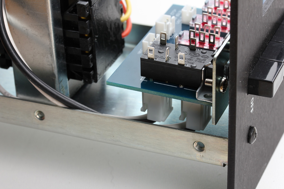
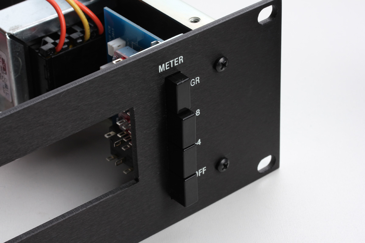
Next mount your meter switch assembly to the rear of the front panel using #4 short silver pan screws. The mounting holes on the bracket are slightly oversized to allow for a bit of adjustment to fit the switch slot in the front panel.
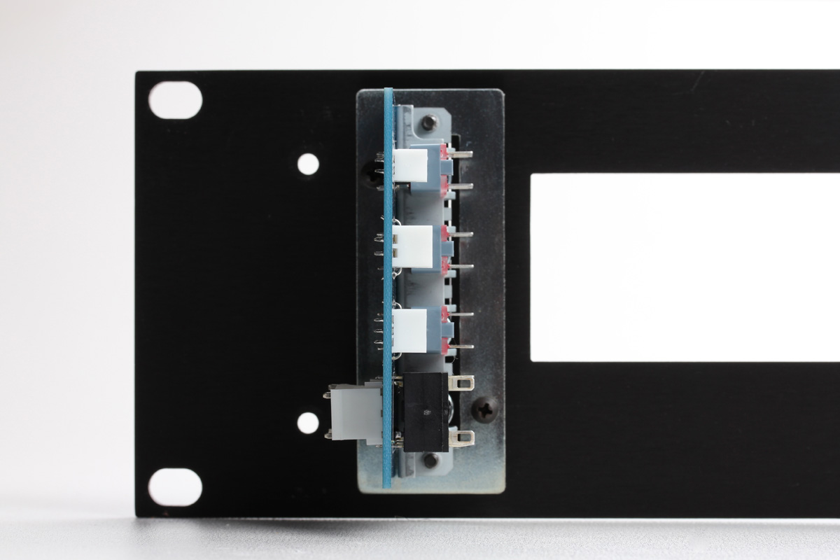
Start with the mounting screws loose and center the switch in the slot before tightening. If you find you have trouble centering it, you can go back and adjust the screws that tighten the bracket to the switch, they also allow for a little adjustment. Once it's securely installed, you can double-check that your switch and bracket are at 90°. If the switch is sitting a little off 90° you can apply mild pressure to the switch to square.
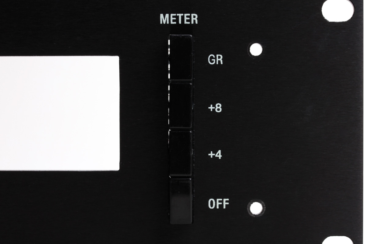
It's important to note that on the FET/RACK there is an "OFF" button, rather than an "ON" button. The unit is turned off by selecting the OFF button. The unit is turned ON when any of the other 3 switches (GR, +4, +8) are selected and the OFF button is disengaged by the interlocking mechanism. For safety, select the OFF position.
Locate the wired connectors for CN4 and CN5 and attach them to the meter PCB now. CN4 is closest to the front panel and has a 2 terminal connector at one end and 2 single long shrouded connectors on the other end. CN5 has the same 2 terminal connectors on either end.
Now set the front panel aside and locate the combined rear and side U panel.
Start by installing your voltage select assembly on the inside of the panel. Locate the bag of screws that contains:
- 4pcs #4 long silver pan screws
- 4pcs #4 silver nut
- 4pcs #4 lock washer
You'll use this hardware to mount the voltage select switch and IEC inlet. You'll note that the small PCB is interfering with access to the mounting holes. Use masking tape to secure the nut and lock washer to the rear side of the mounting holes. Now align the switch in place and thread the screws into the nuts. Remove the tape and tighten.
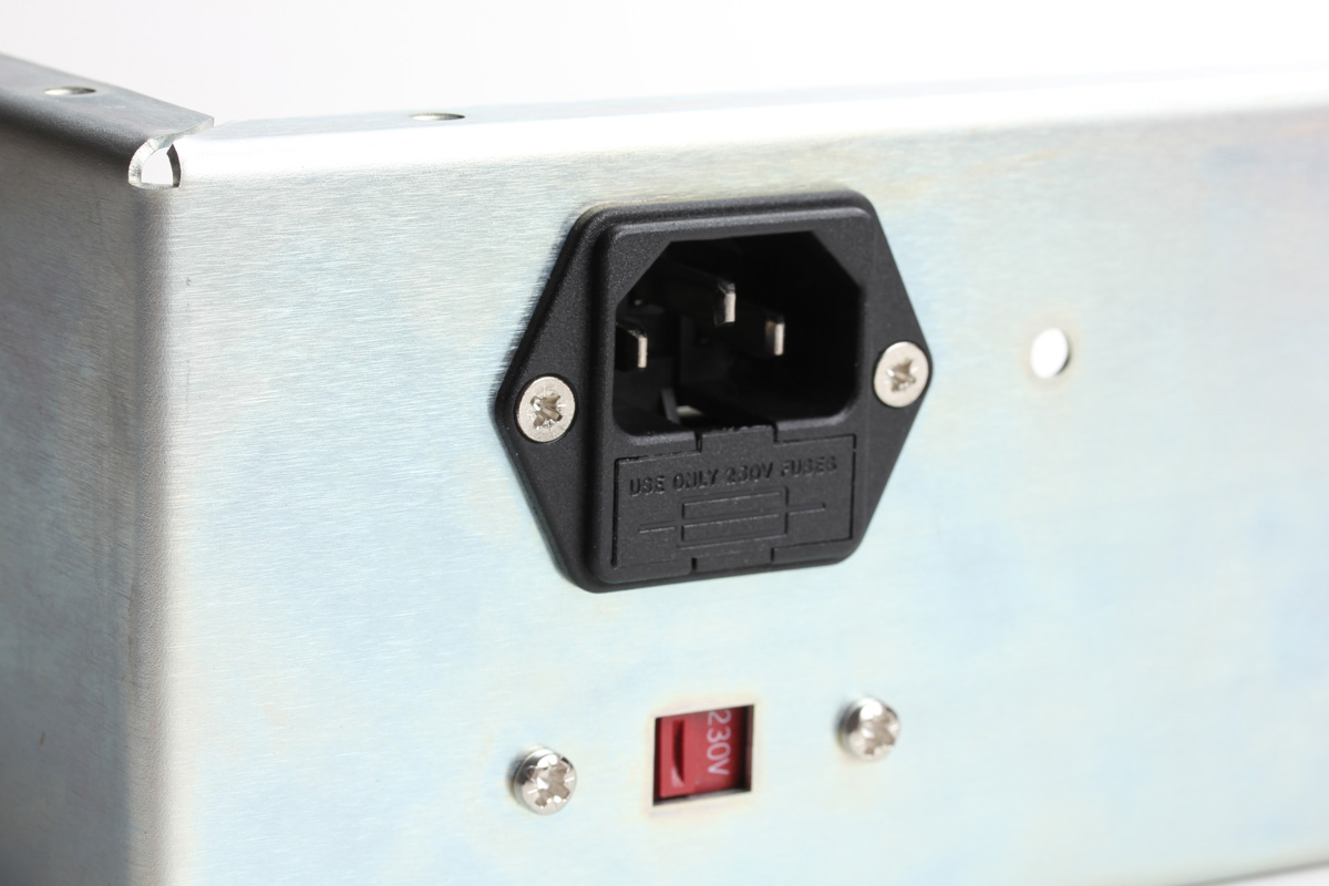
Locate the IEC inlet, insert it and attach wire through the back panel and secure it with the two remaining screws, nuts, and lock washers. The picture above shows the IEC mounted with flat screws, yours will be mounted with pan screws. Note the IEC has a green wire with a yellow stripe attached to it. The wire has a ringed terminal with mounting hardware on the other end. Before installing this wire it's very important that you understand its function, because it may save your life.
This wire is the chassis (enclosure) or safety ground. It grounds the chassis in the event it should become electrically charged. If a wire or component carrying a voltage were to become loose internally and make contact with the chassis, the chassis would become charged. If not grounded, the chassis would hold that charge until it had a path to ground. If you were to touch the charged chassis, your body could become that path to ground and expose you to dangerous levels of current. With this ground in place, any significant electrical contact to the enclosure will immediately be shorted to ground and trip the fuse. There is a hole near the IEC for this wire and ONLY this wire. Do not connect any other components to this mounting hole, as it is dedicated for the safety ground.
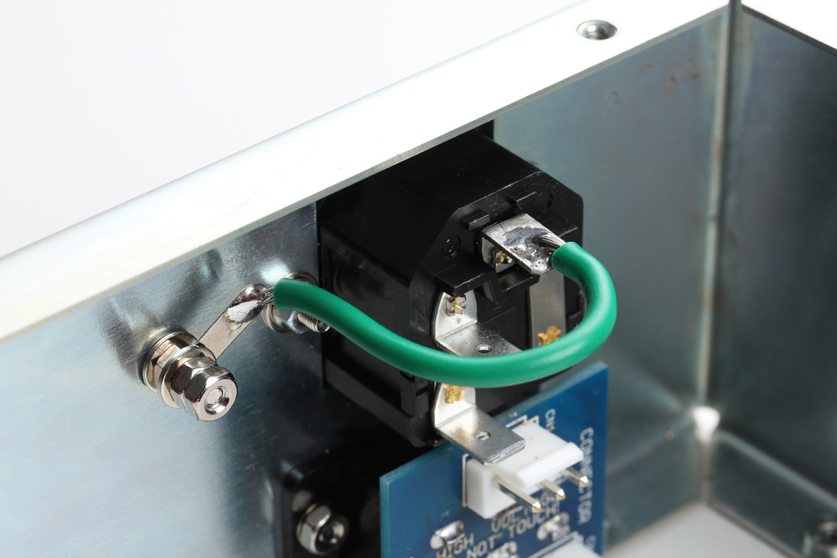
This has to be mounted in a specific way to meet safety standards. From the back panel inward:
#8 screw -> back panel -> #8 lock washer -> ground lug -> #8 lock washer -> #8 nut.
Your finished assembly will look a little different than pictured. The ground lug will arrive soldered to the terminal with the hardware on the screw in the correct order.
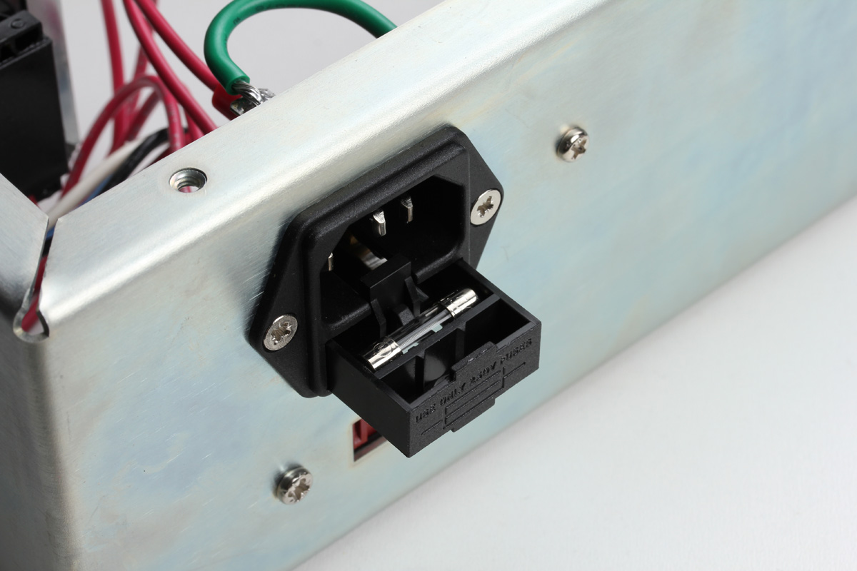
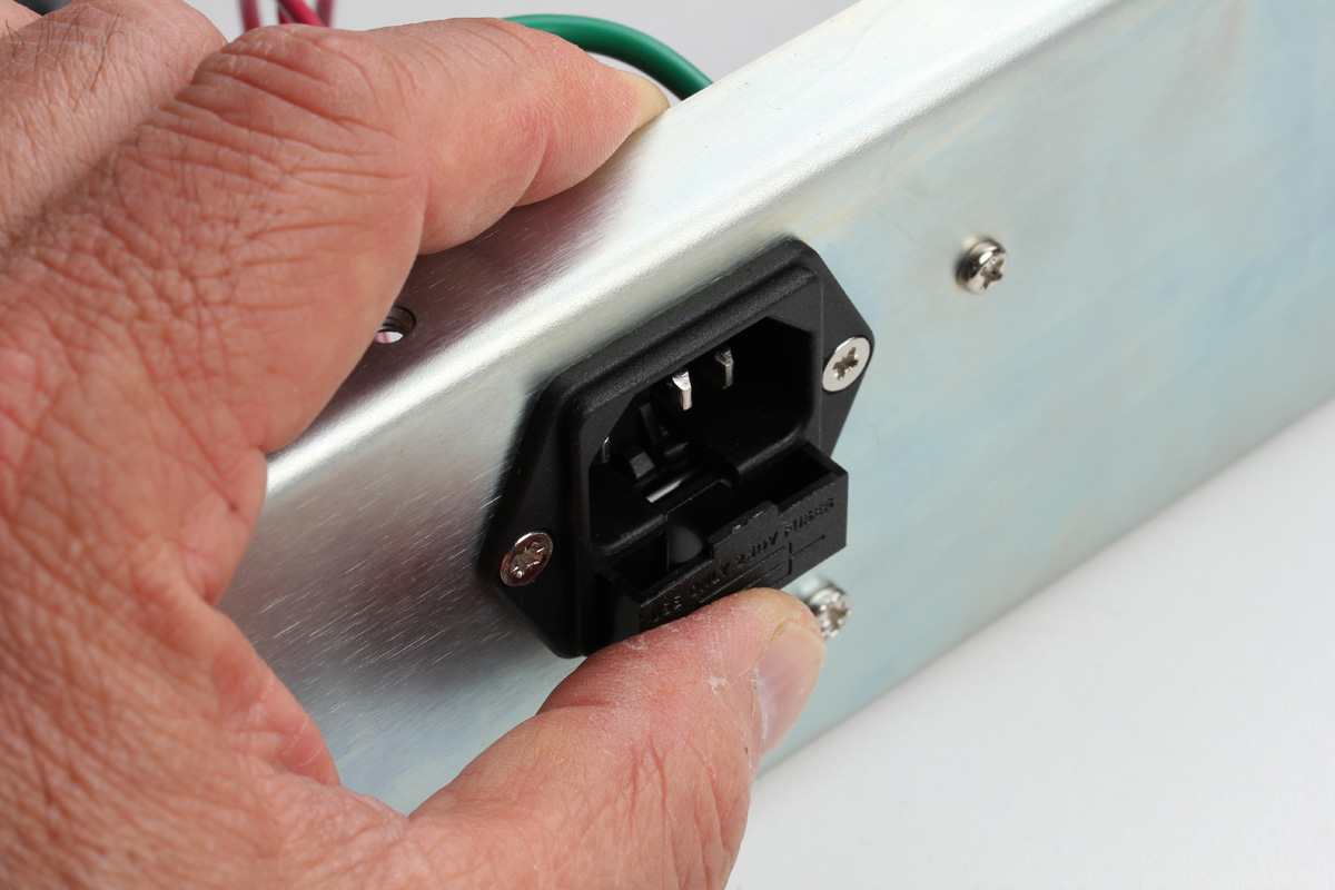
You can now insert the fuse as shown and press the drawer firmly in place until it closes completely.
Next, install the power transformer on the side panel and secure in place using the bag containing two #8 machine screws, nuts, and lock washers. Your side panel may be set up for horizontal or vertical power transformer mounting. Make sure your four connector primary wires are closest to the IEC inlet.
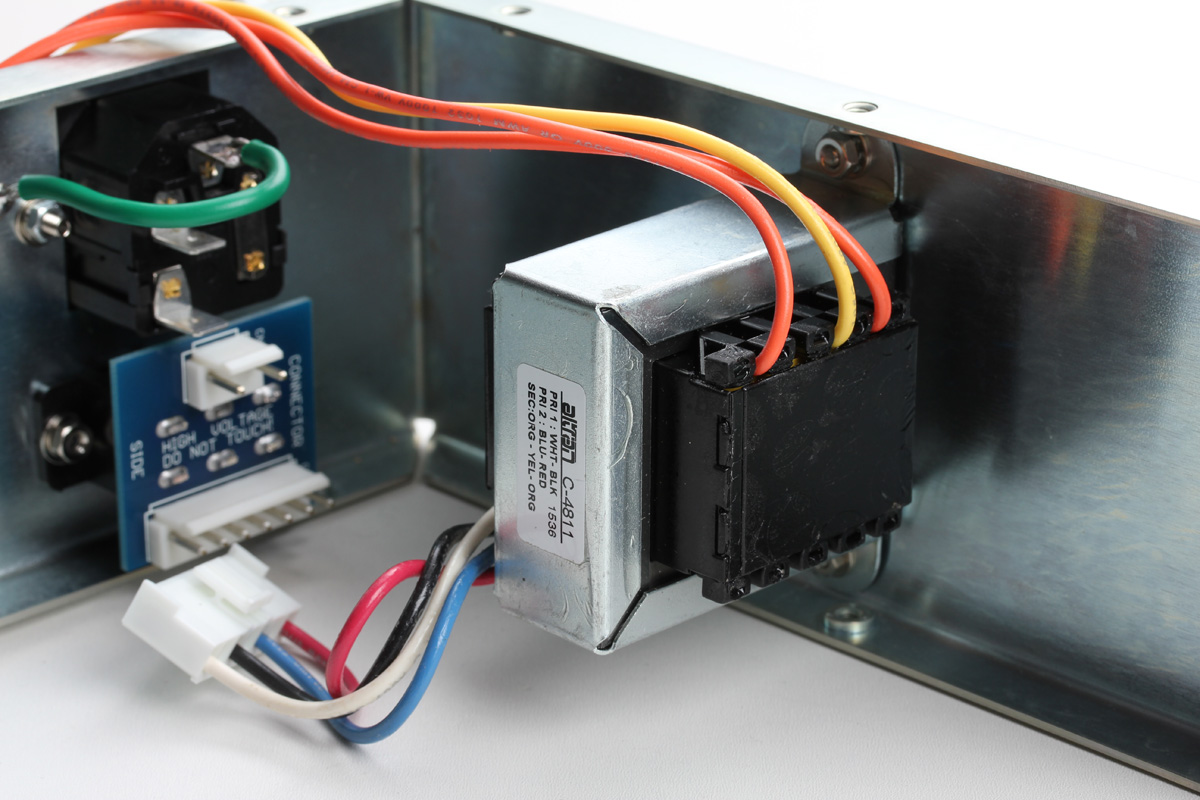
Now connect the 7 terminal power transformer primary to the voltage select CN13. All these connectors are designed to fit in one direction. It should be VERY obvious, and you should not need to force anything.

Next, temporarily secure the main PCB to the back panel using the three L brackets and #4 short silver pan screws. You must secure the PCB to the back panel with all 3 L brackets. In addition to providing structural support, they also ground different points of the main PCB to the chassis. Your power supply will not function properly unless all 3 brackets are installed.
Secure the front panel to the enclosure using the #6 pan screws. If you have a black front panel these four screws will be black, for the blue stripe they will be silver. You'll note that the CN4 and CN5 wires will need to be tucked in tightly to make it all fit. This is normal and why we installed them first.
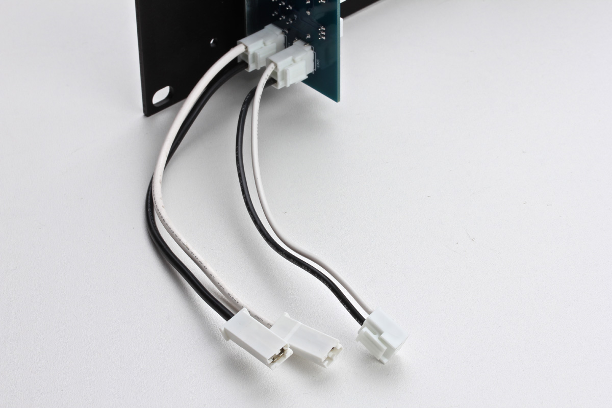
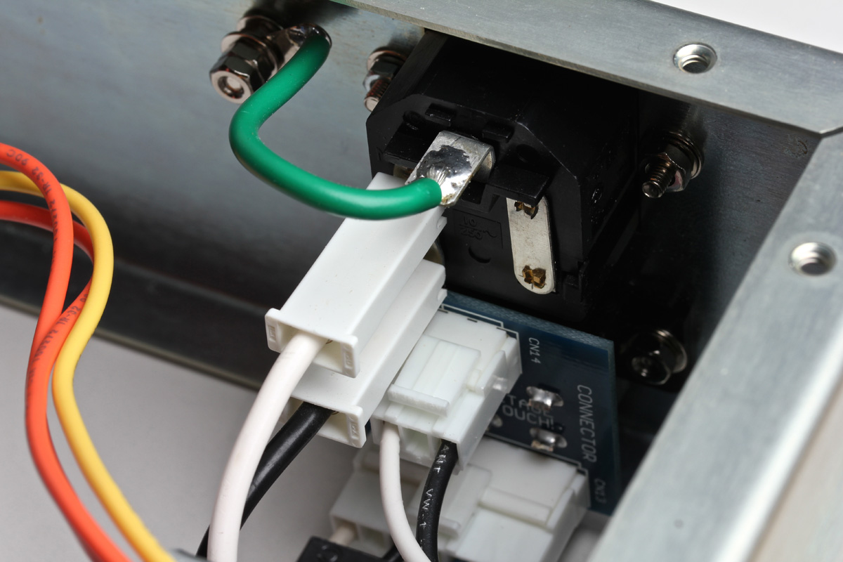
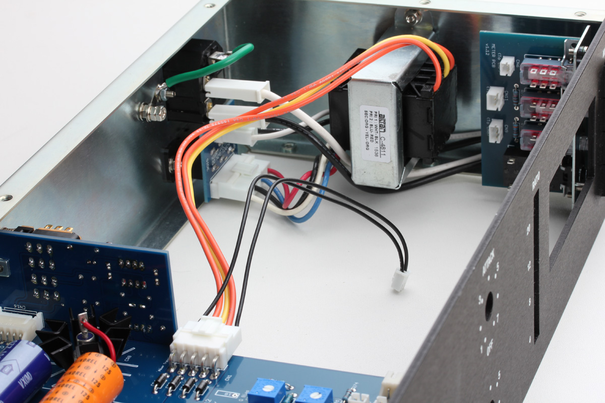
Now you can connect the 2 terminal connectors from CN5 to CN14. Connect the two long shrouded connectors from CN4 to the IEC. the white connector to the neutral terminal marked "N" and the black to the live terminal marked "L". Your IEC will probably have the terminals rotated 90 degrees, but they are labeled the same.
Here is the bottom view of the same assembly.

Now connect the 5 terminal power transformer secondary connector to the main PCB CN1. You can leave the smaller wire assembly attached to it disconnected for now. We'll use that to light the VU meter later.
With these steps carefully completed you should have a functioning power supply. Let's test it.
STOP!!!!!
CHECK YOUR VOLTAGE SELECTOR SWITCH AND CONFIRM ITS SET TO THE APPROPRIATE MAINS VOLTAGE FOR YOUR REGION.
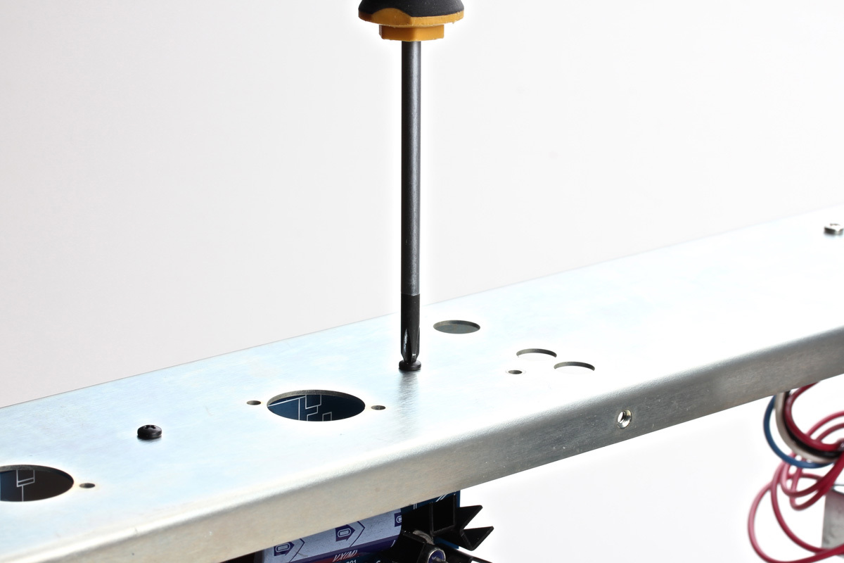
Grab your DMM and place the common probe, traditionally black, in one of the top panel mounting holes. We need to establish a ground reference and since we know our enclosure should be ground, why not use it as the reference point.
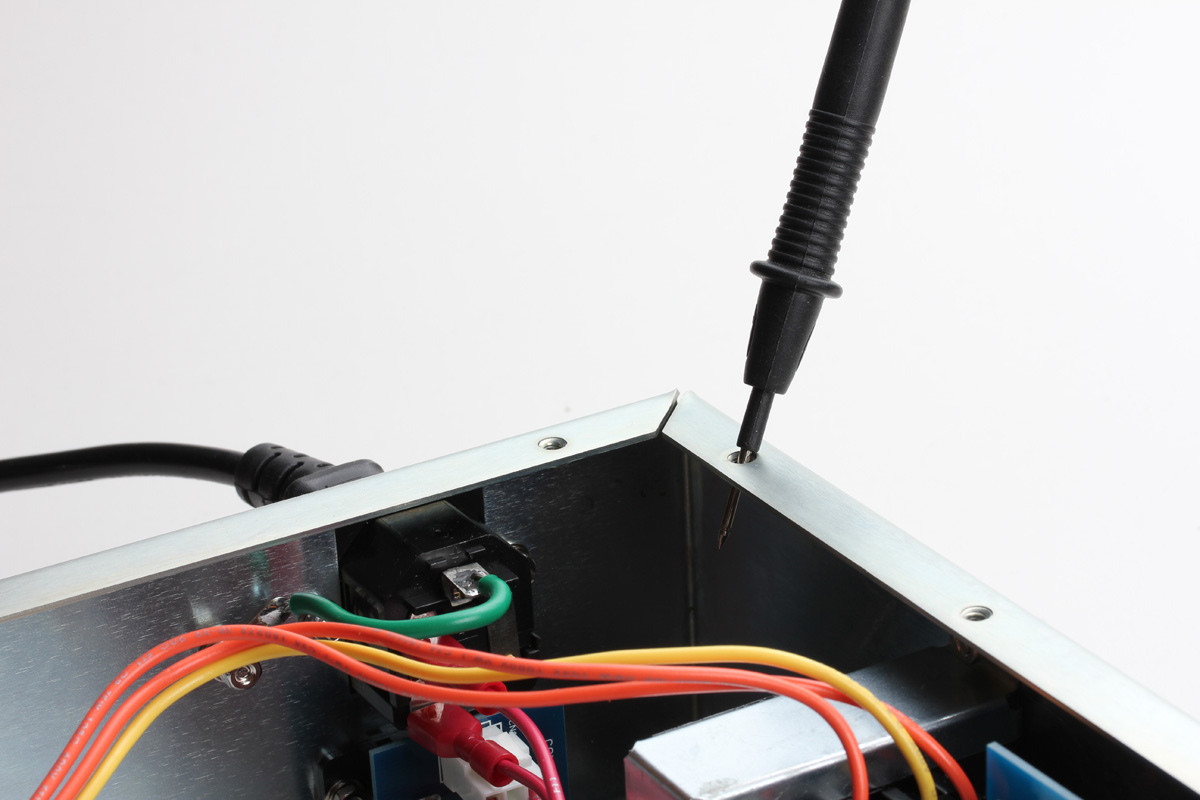
Now set your DMM to read resistance in ohms (Ω). Place your measuring probe, typically red, on the ground tab on the IEC inlet. This is the tab with the green/yellow wire. You should read a very low resistance here, around 0.2Ω depending on the added resistance of the probe wire and the quality of your meter. Anything above 1Ω is cause for concern.

Now we'll test the power supply. Set your DMM to read DC voltage. If your meter is not auto-scaling, set it appropriately to read 10 to 30V DC. Turn the unit ON by selecting "GR" on the meter switch.
Stand away from the board for the first few seconds. When large electrolytic caps (orange and purple) fail, they tend to with a small explosion. You do not want to get any molten capacitor bits on your skin.
You may detect a slight burning smell, this is normal and most likely coming from the large stud diode. Smoke is NOT normal. Do remember that your unit has an appropriately rated fuse, so any catastrophic event will blow your fuse and cut power to the unit. If you blow fuses, DO NOT increase the rating. You have an error and replacing the fuses with higher rated fuses is unsafe.
With your common probe still in the top panel mounting hole, carefully touch your measurement probe to the cathode of CR8 as shown.
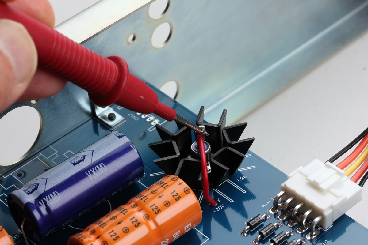
You should read +30V DC here ±5%.
Now place you measuring probe on the anode of CR9 which is labeled with a "-10V".
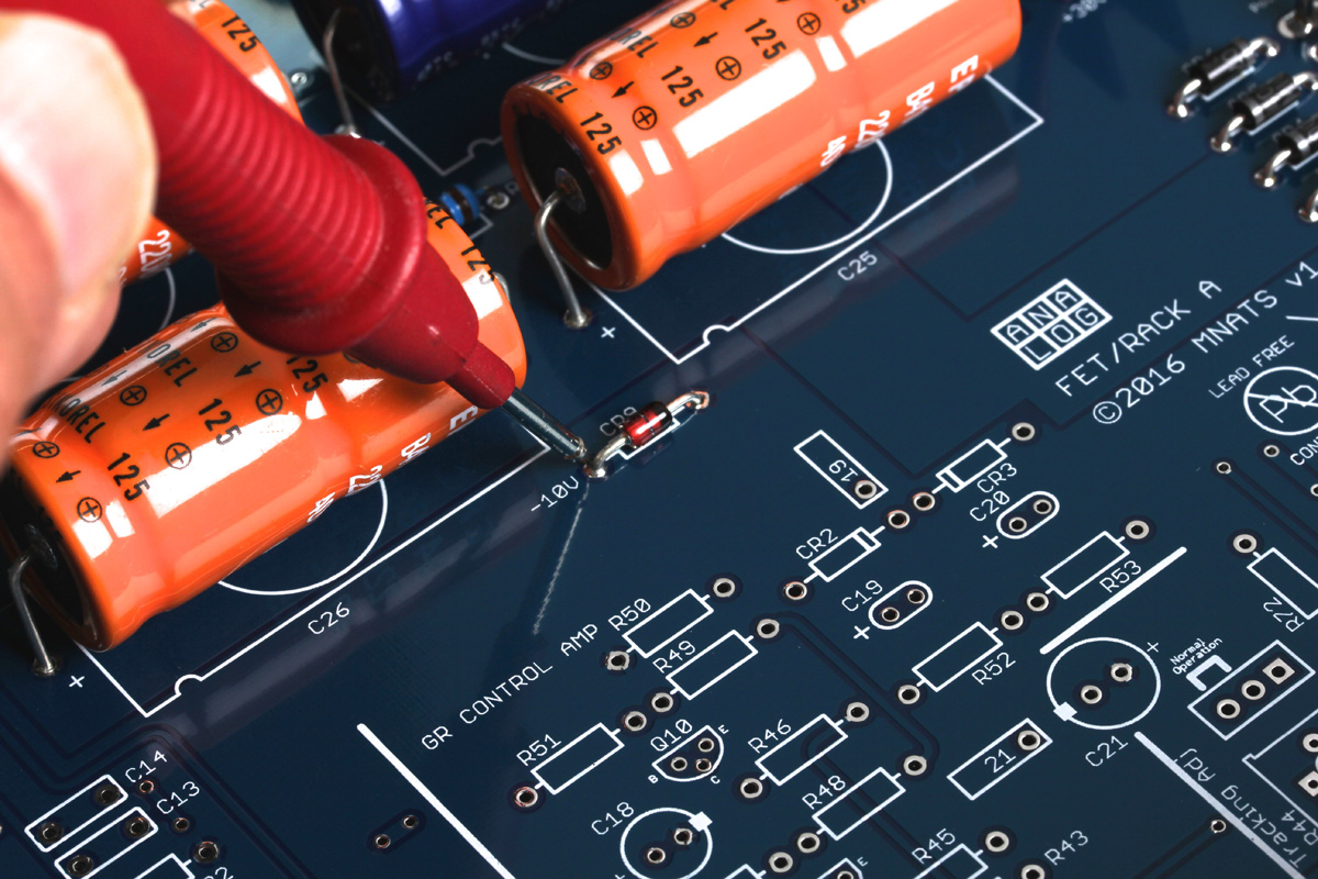
You should read -10V DC ±10% at this test point.
If all the readings are as expected, congratulations you have a working power supply!